
Operation Manual
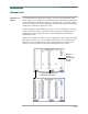
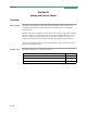
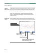
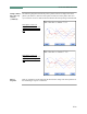


Table Of Contents
- Title Page - Energy Platform User Guide
- Table of Contents
- Chap 1 Getting Started
- Chap 2 Voltage Measurement Cable and Current Probe Connections
- Chap 3 View Real Time Data
- Chap 4 Instrument Settings
- Chap 5 Start Menu
- Chap 6 Advanced Setup Options
- Chap 7 View Event Data
- Chap 8 Reports
- Chap 9 Downloading Events
- Appendix A Optional Accessories
- Appendix B Technical Specifications
- Appendix C Battery Specifications and Replacement Procedure
- Appendix D User Replaceable Parts List
- Appendix E Common Circuit Connections
- Appendix F Event Classification
- Appendix G Energy Platform Menu Structure
3-21
CH 3/ View Real Time Data
Sample 3-Phase,
three wire wye
rotation
(continued)
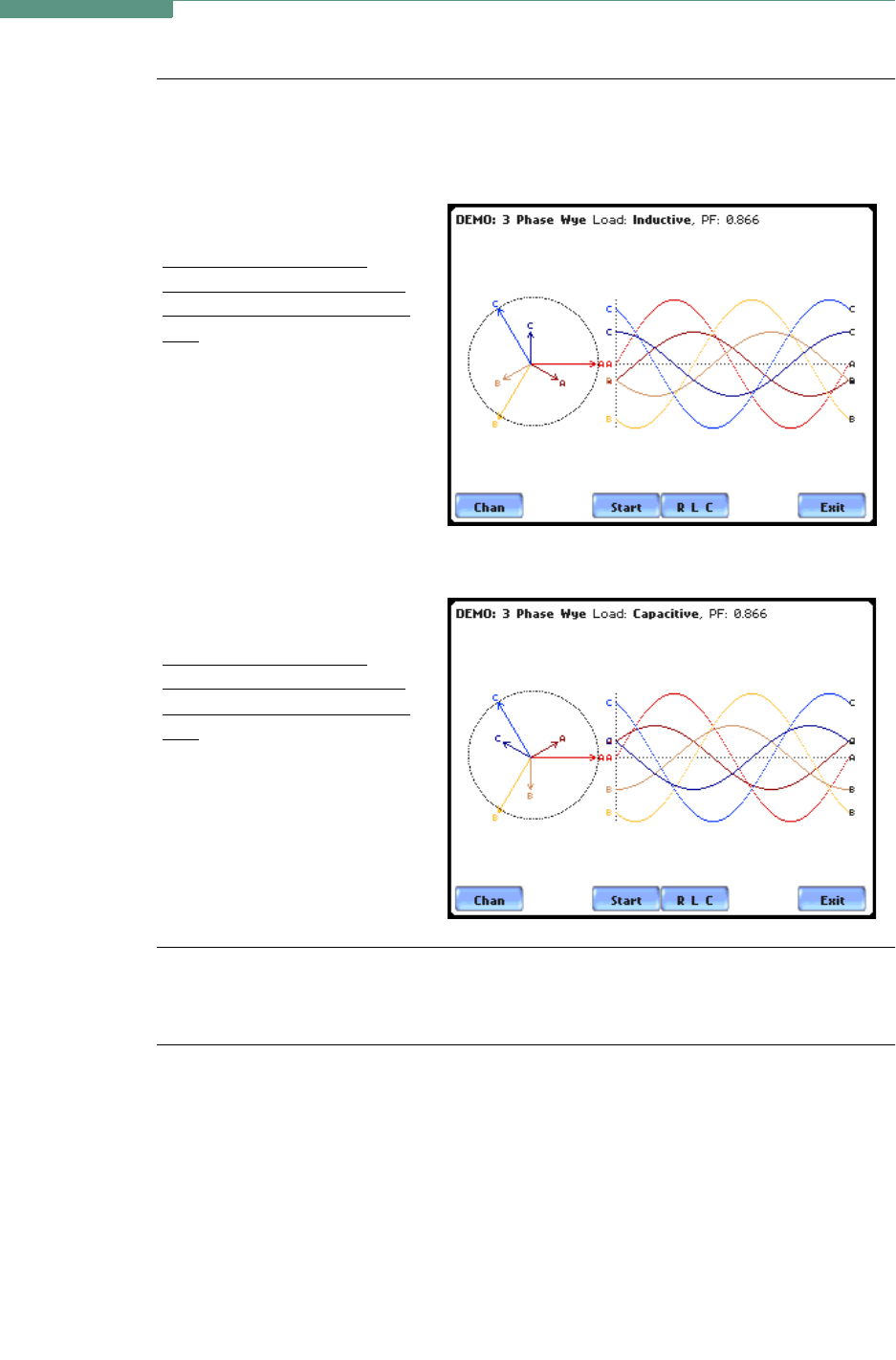
The following diagrams describe the positive phase rotation of voltage and current
phasors (for Resistive, Inductive and Capacitive loads) for a three phase, three wire
wye connection. An arrow head on the line indicates direction pointing toward the load.
Three phase vectors are
displayed as three lines, 120
degrees apart in an Inductive
load
Three phase vectors are
displayed as three lines, 120
degrees apart in a Capacitive
load
Phasor
diagrams
Refer to Appendix E for the diagrams that describe the voltage and current phasors for
the standard type of power connections.
MARK243
MARK244