
Operation Manual
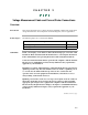
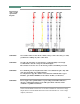
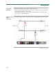
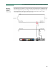
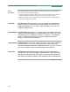
Table Of Contents
- Title Page - Energy Platform User Guide
- Table of Contents
- Chap 1 Getting Started
- Chap 2 Voltage Measurement Cable and Current Probe Connections
- Chap 3 View Real Time Data
- Chap 4 Instrument Settings
- Chap 5 Start Menu
- Chap 6 Advanced Setup Options
- Chap 7 View Event Data
- Chap 8 Reports
- Chap 9 Downloading Events
- Appendix A Optional Accessories
- Appendix B Technical Specifications
- Appendix C Battery Specifications and Replacement Procedure
- Appendix D User Replaceable Parts List
- Appendix E Common Circuit Connections
- Appendix F Event Classification
- Appendix G Energy Platform Menu Structure
2-6
Connecting Voltage Measurement Cables, continued
Connection
guidelines
Follow these guidelines when making voltage connections.
• Refer to the measurement cable set figure for color coding of probes that connect to
input channel connectors A, B, C, and D.
• Channel D input has plus (+) and minus (-) differential inputs. All voltage inputs
have a range of 1 to 600 Vrms max.
Example: Single
phase
connection
The following figure shows a voltage connection to a single phase circuit for channel
A.
Continued on next page
EP-12.vsd