
User manual

GMC-I Messtechnik GmbH 31
12 Maintenance
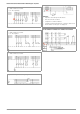
12.1 Firmware Revision and Calibration Information
See section 3.4.
12.2 Rechargeable Battery Operation and Charging
Check to make sure that no leakage has occurred at the
rechargeable batteries in the Z502H battery pack at short, regular
intervals, or after the instrument has been in storage for a lengthy
period of time.
Note
Prior to lengthy periods of rest (e. g. holiday), we recom-
mend removing the (rechargeable) batteries. This helps to
prevent excessive depletion or leakage of batteries,
which, under unfavourable circumstances, may cause
damage to the instrument.
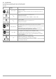
If battery voltage has fallen below the allowable lower
limit, the pictograph shown at the right appears. “Low
Batt!!!” is also displayed along with a battery icon. The instrument
does not function if the batteries have been depleted excessively,
and no display appears.
Attention!
!
Use only the Z502H battery pack.
Attention!
!
Use only the Z502R charger (available as an accessory)
to charge batteries which have already been inserted into
the test instrument.
Make sure that the following conditions have been fulfilled be-
fore connecting the charger to the charging socket:
– Rechargeable batteries have been installed with
correct polarity (not standard batteries).
– The test instrument has been disconnected from the
measuring circuit at all poles.
– The instrument must remain off during charging.
If the batteries or the battery pack have not been used or
recharged for a lengthy period of time, thus resulting in excessive
depletion:
Observe the charging sequence (indicated by the LED at the
charger) and initiate a second charging sequence if necessary
(disconnect the charger from the mains and from the test instru-
ment to this end, and then reconnect it).
12.2.1 Charging Procedure with the Z502R Charger (accessory)
➭ Insert the correct mains plug for your country into the charger.
Attention!
!
Make sure that rechargeable batteries have been in-
serted (not normal batteries). We recommend the use of
rechargeable NiMH batteries (eneloop type).
➭ Connect the charger to the test instrument with the barrel
connector, and then to the 230 V mains with the interchange-
able plug.
Attention!
!
Do not switch the test instrument on during charging. Monitor-
ing of the charging process by the microprocessor might
otherwise be disturbed, in which case the charging times
specified in the technical data can no longer be assured.
➭ Please refer to the operating instructions included with the
charger regarding the meanings of LED displays during the
charging process.
➭ Do not disconnect the charger from the test instrument until
the LED lights up green.
12.3 Fuses
If a fuse has blown due to overload, a corresponding error mes-
sage appears at the display panel. The instrument’s voltage mea-
suring ranges are nevertheless still functional.
12.3.1 Melting Fuse
This fuse is active in all resistance measuring ranges except for
voltage measurement. A replacement fuse is included in the bat-
tery compartment (FF315mA/1000V).
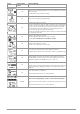
Checking the Fuse
If a resistance measuring range is selected
with the rotary switch with a blown or defec-
tive fuse in the instrument, and if measure-
ment is started with the START or CONTIN.
key, a pop-up window with the “blown fuse”
icon appears. Prerequisite: The + and COM
measurement jacks are not short circuited.
This error message must be acknowledged and cleared by press-
ing the ESC key.
➭ Eliminate the cause of failure and replace the blown fuse.
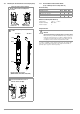
Replacing the Fuse
Attention!
!
Disconnect the instrument from the measuring circuit be-
fore opening the battery compartment lid in order to re-
place the fuse (refer to page 3 for location)!
The rotary switch must be in the OFF position when the
fuse is replaced.
Attention!
!
Incorrect fuses may cause sever damage to the instru-
ment.
Only original fuses from GMC-I Messtechnik GmbH as-
sure the required protection by means of suitable blow-
ing characteristics.
Short-circuiting of fuse terminals or the repair of fuses is
prohibited!
The instrument may be damaged if fuses with incorrect
ampere ratings, breaking capacities or blowing charac-
teristics are used!
➭ Open the battery compartment lid by loosening the two
screws.
➭ Remove the defective fuse and replace it with a new one. A
replacement fuse is included in the battery compartment.
➭ Insert the new fuse.
➭ Replace the battery compartment lid and retighten the
screws.
12.3.2 Electronic Fuse
This fuse protects low-resistance (Rlo) and resistance measure-
ments (kΩ) from overloading (electronic hardware circuit).
A pop-up window appears when the fuse
blows.
This error message must be acknowledged
and/or cleared by pressing any desired key.
➭ Eliminate the cause of overloading.
BAT