
User manual

18 GMC-I Messtechnik GmbH
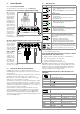
6.5 Discharging the Device Under Test
Attention!
!
If measurement is performed at a capacitive object such
as a long cable, it becomes charged with up to approx.
1000 V!
Touching such objects is life endangering!
When an insulation resistance measurement has been performed
on a capacitive object it is automatically discharged by the instru-
ment after measurement has been completed. Contact with the
device under test must be maintained to this end. The falling volt-
age value can be observed at the U display.
Do not disconnect the DUT until less than 10 V is displayed for U!
6.6 Evaluation of Measured Values
Instrument measuring error must be taken into consideration in
order to assure that the limit values set forth in DIN VDE regula-
tions are not fallen short of. The required minimum display values
for insulation resistance can be determined with the help of the
table, “
Display Values in Consideration of Measuring Uncertainty
”, o n
page 30. These values take maximum device error into consider-
ation (under nominal conditions of use). Intermediate values can
be interpolated.
6.7 Polarization Index Measurement
In the case of electrical machines which include components with
windings (generator and motor windings), it’s advisable to con-
duct polarization index testing. This procedure involves expanded
testing of insulation resistance. The accumulation of moisture and
contamination on windings can be detected as reduced insulation
resistance.
DC measuring voltage from the METRISO XTRA is applied to the
insulation for a duration of 10 minutes to this end. Measured val-
ues are documented after one minute, and after ten minutes. If
the insulation is good, the value measured after ten minutes is
higher than the value measured after one minute. The relationship
between the two measurement values is the polarization index.
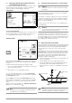
The molecules within the insulation are aligned due to the applica-
tion of measuring voltage over a long period of time, resulting in
polarization. The polarization index indicates whether or not the
molecules contained in the insulation can still be moved, thus
allowing for polarization. This, in turn, is an indication of the condi-
tion of the insulation. The more freely the charge carriers can be
moved, the better is the condition of the insulation.
The following rules apply in general:
PI value < 1: Troubleshooting is required.
PI value = 1 to 2: Maintenance is advisable.
PI value = 2 to 3: DUT is OK!
No immediate action is required.
Preventive maintenance can be planned
according to workload.
PI values > 3: Error-free device under test
Applications
Determination of moisture and contamination levels
Attention!
!
For PI measurement, test instrument on-time should be
set to OFF (see section 3.4, “Device Settings – SETUP’’).
Note
Z550A Option
Use of the measurement cable with remote start/stop is
not advisable for polarization index measurement PI or
absorption index measurement DAR, because measure-
ment is only conducted as long as the START key is
pressed and held.
In order to assure that the entire measuring
sequence is nevertheless executed, start each measurement
with the
START
key at the test instrument only.
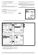
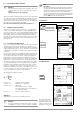
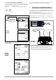
Set Parameters
Start Measurement
The selected polariza-
tion index menu is only
displayed until the rotary
switch is activated or the
parameter is changed.
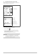
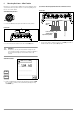
PI
R
10min
R
1min
--------------=
Polarization Index
Test voltage switch position:
50 V / 100 V / 250 V / 500 V / 1000 V
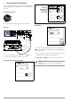
Absorption index
Insulation resistance
START