
User manual

GMC-I Messtechnik GmbH 17
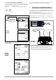
6.3 Measurement with Rising Test Voltage (ramp function)
and Variably Adjustable Final Value
The “Uramp” rising test voltage function (ramp function) is used to
detect weak points in the insulation, as well as to determine
response voltage for voltage limiting components.
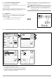
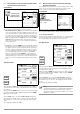
Set Parameters
Refer to section 4.7 regarding how to set the final ramp value. The
selected nominal voltage value is displayed in the main menu.
❏ Pole Selection Report Entry
The poles between which testing takes place can only be entered
here for reporting purposes. The entry itself has no influence on
the actual polarity of the test probes or pole selection.
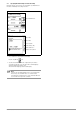
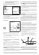
Start Measurement
After briefly pressing the START key, test voltage is continuously
increased until the specified nominal voltage U
N
(100 ... 1000 V) is
reached.
Insulation measurement with rising test voltage is ended:
• As soon as specified maximum test voltage U
N
is reached and
the measured value is stable
or
• After sparkover occurs at breakdown voltage
As soon as the final ramp value is reached, the Uramp LED lights
up green. If the final ramp value is not reached due to sparkover,
the Uramp LED lights up red.
U is the voltage which is measured at the test probes during and
after testing. This voltage drops to a value of less than 10 V after
measurement (see section 6.5, “Discharging the Device Under
Test’’).
Highest achieved test voltage U or any triggering or breakdown volt-
age which occurs is displayed for U
INS
.
Note
Measurement can be stopped at any time by pressing
the START key or the CONTIN. key.
6.4 Insulation Resistance Measurement – Special Conditions
Attention!
!
Insulation resistance can only be measured at voltage-
free objects.
If measured insulation resistance is less than the selected limit
value, the limit LED lights up red.
If an interference voltage of roughly
≥ 15 V is present and “U
EXT
– Interference Voltage” appears in a pop-up window, insulation
resistance is not measured. In the case of interference voltage >
50 V, the “> 50 V” LED lights up.
In 3-phase systems, all conductors (L1, L2, L3 and N) must be
tested against PE!
Attention!
!
Do not touch the instrument’s terminal contacts during
insulation resistance measurements!
If nothing has been connected to the terminal contacts, or if a
resistive load component has been connected for measurement,
your body would be exposed to a current of approximately 1 mA
at a voltage of 1000 V. The noticeable shock may lead to injury
(e.g. resulting from a startled reaction etc.).
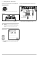
6.4.1 Measurements with the Guard Cable
The measurement of very high resistances necessitates extremely
minimal measuring current and may be rendered problematic as a
result of influences such as electromagnetic fields, humidity or
surface pollution. An accurate test set-up is thus absolutely
essential.
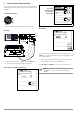
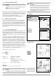
A guard cable must be used for measurements within a range of
100 GΩ (10 GΩ) … 1TΩ, in order to prevent surface current from
distorting measurement results. The guard rings prevent current
at the surface of the insulation material from flowing from the
+measurement cable to the –measurement cable, instead of
through the insulation material itself.
➭ Insert the plug from the guard cable into the appropriate jack
in the test instrument.
➭ Plug the alligator clip onto the guard cable test probe.
➭ Connect the alligator clip to the guard ring between the two
measuring points at the insulation material under test.
➭ Refer to section 6.1 to section 6.3 regarding the measuring
sequence.
Note
The following materials can be used as guard rings: alu-
minum foil, copper foil or metallic hose clamps.
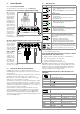
Maximum test voltage
100 V ... 1000 V
(final ramp value)
Max. 1 mA (at 1 KΩ/V)
Current load:
START
+Measurement Cable
–Measurement Cable
Guard Cable
Conductor
Insulation
Material
Guard Rings
Contact Ring
(COM)