
User manual

16 GMC-I Messtechnik GmbH
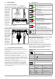
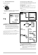
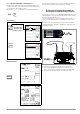
6.1 Measuring with Constant Test Voltage and Nominal Value
Selection via Rotary Switch Position
Set Parameters
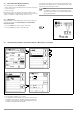
The constant test voltage function offers two options:
• After briefly pressing the START key, specified test voltage UN is
read out and insulation resistance RINS is measured. As soon
as the measured value is stable (settling time may be several
seconds in the case of high cable capacitance values), mea-
surement is ended and the last measured values for RINS and
UINS are displayed. U is the voltage which is measured at the
test probes during and after testing. This voltage drops to a
value of less than 10 V (see section entitled “Discharging the
Device Under Test”.
or
• As soon as you press the CONTIN key, test voltage UN is applied
and insulation resistance RINS is measured. Do not press the
key again in order to stop measurement until the measured
value has settled in (settling time may be several seconds in
the case of high cable capacitance values). Voltage U, which
is measured during testing, corresponds to voltage UINS.
After once again pressing the CONTIN key, measurement is
ended and the last measured values for RINS and UINS are
displayed. U drops to a value of less than 10 V after measure-
ment (see the section entitled “Discharging the Device Under
Test”.
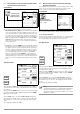
Start Measurement
After pressing the START key, nominal voltage U
N
(50 ... 1000 V)
selected with the rotary switch is applied until the measured val-
ues settles in.
After pressing the CONTIN. key, the previously selected test voltage
or nominal voltage U
N
(50 to 1000 V) is applied until the CONTIN.
key is pressed once again.
U is the voltage which is measured at the test probes during and
after testing. This voltage drops to a value of less than 10 V after
measurement (see section 6.5, “Discharging the Device Under
Test’’).
Test voltage U
is displayed for U
INS
.
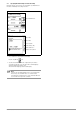
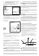
6.2 Measurement with Constant Test Voltage and Variably
Adjustable Nominal Value
A test voltage which deviates from nominal voltage, and is usually
lower, can be selected for measurements at sensitive compo-
nents, as well as systems with voltage limiting devices.
Set Parameters
Refer to section 4.7 regarding how to enter the variable voltage.
The selected nominal voltage is displayed in the main menu.
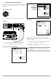
❏ Pole Selection Report Entry
The poles between which testing takes place can only be entered
here for reporting purposes. The entry itself has no influence on
the actual polarity of the test probes or pole selection.
Start Measurement
After pressing the START key, nominal voltage U
N
(50 to 1000 V)
entered previously via the parameters menu is applied until the
measured values settles in.
After pressing the CONTIN. key, the previously selected test voltage
or nominal voltage U
N
(50 to 1000 V) is applied until the CONTIN.
key is pressed once again.
U is the voltage which is measured at the test probes during and
after testing. This voltage drops to a value of less than 10 V after
measurement (see section 6.5, “Discharging the Device Under
Test’’).
Test voltage U
is displayed for U
INS
.
Note
The instrument’s batteries are rapidly depleted during the
insulation resistance measurement. Stop continuous
measurement with “constant test voltage” as soon as the
display has settled in.
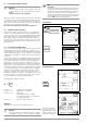
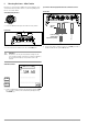
Polarization index
Test voltage switch position:
50 V / 100 V / 250 V / 500 V / 1000 V
Absorption index
Insulation resistance
START
CONTIN
Variable test voltage
50 V ... 1000 V
(constant nominal value):
START
CONTIN