
User manual

GMC-I Messtechnik GmbH 11
4 General Operation
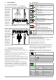
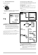
4.1 Connecting the Instrument
The test leads are connected to the “+” and “COM” jacks.
Special Case:
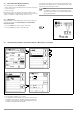
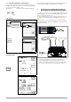
Test Probe for Remote Triggering (Option Z550A)
When inserting
the 3-pole plug,
make sure that
the jack plug is
inserted in the
START/STOP
position. Press
and align the 3-
pole plug such
that it is placed
flush on the con-
nection terminal.
This is the only
way to assure
that the three
contacts of the
jack plug are
properly con-
nected with the command cables.
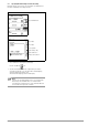
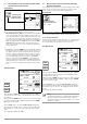
Special Case: Measuring High-Value Resistance with the KS-C Probe (Option)
When measuring
electrostatic dis-
charge capacity
for floor cover-
ings, the shielded
cable should be
connected to the
COM and SHIELD
jacks (KS-C
accessory set,
“cable set con-
sisting of mea-
surement cable
and high-resis-
tance measure-
ment cable for
measurements in the GΩ range”, see diagram). Be sure to
observe color coding.
4.2 Switching On, Monitoring and Switching Off
If supply voltage drops to a value of less than 8.5 V, the
LOW BATT pop-up message appears: No more measurements
can be started.
If battery voltage falls below the allowable limit value of 8.0 V, the
instrument cannot be switched on, or it is switched off.
Measurements cannot be started in the resistance measuring
ranges in the event of interference voltage.
The instrument only switches itself off automatically after comple-
tion of an (automatic) measuring sequence, and after the prede-
termined on-time has expired (see page 8). On-time is reset to its
original value as defined in the setup menu, as soon as any key or
the rotary function switch is activated.
If the instrument is switched off automatically with the rotary
switch in any position other than OFF, it can be reactivated by
pressing the ESC key. The instrument is also reactivated if the
rotary switch is activated and turned through the OFF position.
The instrument can be switched off manually by turning the rotary
switch to the OFF position.
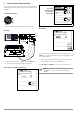
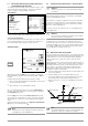
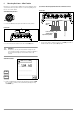
4.3 Optical Indicators
1
Function testing should be executed at regular intervals (see following
section regarding testing the LEDs).
Testing the LED which Indicates Detection of Interference Voltage
when Switched Off – OFF Switch Position
➭ Apply a voltage of greater than 50 V (+ and COM jacks).
➭ Turn the rotary switch to the V position.
➭ Read the voltage value at the LCD.
➭ Turn the rotary switch to the OFF position.
Test results: If applied voltage is unchanged and the LED which
indicates the detection of interference voltage lights up red, the
LED is OK. In this case, the LED reliably indicates interference
voltage even when the instrument is switched off. We recom-
mend executing this test at regular intervals.
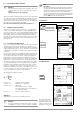
METRISO XTRA Measuring Functions, Measuring Ranges and
Limit Values
START/STOP SHIELD COM
Option Z550A
+
KS-C
(Z541F)
+
C
O
M
SH
I
E
L
D
LED Status
Function – Cause
Limit Value Indication
– Measured insulation resistance does not violate the limit
value.
– Measured low-resistance Rlo does not violate the limit
value.
Limit Value Indication
– Measured insulation resistance has fallen short of the
selected limit value.
– Measured low-resistance Rlo does has exceeded the
permissible limit value.
Indication of ramp characteristics
– Maximum ramp voltage (upper voltage limit) has been
reached (without breakdown).
Indication of ramp characteristics
– Maximum ramp voltage (upper voltage limit) has not been
reached (due to breakdown).
Breakdown voltage is displayed.
Interference voltage in switched-off condition
1
and signal-
lings of test voltage during insulation measurement
Dangerous voltage of greater than 50 V is present at the mea-
surement inputs:
– Initialization of insulation resistance and
low-resistance measurement is disabled.
– High test voltage is applied to the measuring terminals
(Riso/Rins, PI and DAR) during insulation measurement
Detection of interference voltage in the on-state
in the resistance measuring ranges after starting measurement
The value of interference voltage is displayed in addition to signalling
in the resistance measuring ranges for as long as it is present.
Measuring Ranges
R
ISO
/ R
INS
U = 50, 100, 250, 500, 1000 V
R
ISO
/ R
INS
Uvar = 50 ... 1000 V
R
ISO
/ R
INS
Uramp (U ) = 100 ... 1000 V
R 10 ... 10 kΩ
R
LO
0.01 ... 10 Ω
U 0 ... 1000 V
Limit Values
Limit R
ISO
/ R
INS
Fixed setting 50 kΩ @ U
ISO
/U
INS
= 50 V
Fixed setting 100 kΩ @ U
ISO
/U
INS
= 100 V
Fixed setting 500 kΩ @ U
ISO
/U
INS
= 250 V
Fixed setting 1 MΩ @ U
ISO
/U
INS
= 500 V
Fixed setting 1 MΩ @ U
ISO
/U
INS
= 1000 V
Fixed setting 1 MΩ @ U
ISO
/U
INS
= Uvar
PI limit Adjustable 1.0, 1.1, 1.5, 2.0, 3.0, 4.0
DAR limit Adjustable 1.25, 1.6
Limit R
LO
Fixed setting 2 Ω
Limit
Green
Limit
Red
Uramp
Green
Uramp
Red
Red
!
Limit