
User Manual

20 GMC-I Messtechnik GmbH
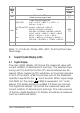
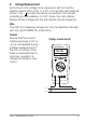
12 Continuity Test and Diode Test
• Verify that the device under test is electrically dead. Exter-
nal voltages would falsify the measured results!
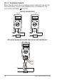
12.1 Continuity Test
• Set the function selector switch (6) at „Ω“, then press the
yellow multi-function pushbutton (5). The multimeter
acknowledges turn-ON with an acoustic signal.
• At the same time, (18) appears on the LCD and „OL“ is
displayed on the main display.
• An acoustic signal is generated whenever the reading is
less than 30 Ω.
12.2 Diode Test
• Set the function selector switch (6) at „Ω“, then press the
yellow multi-function pushbutton (5) twice. The multimeter
acknowledges turn ON with an acoustic signal.
• At the same time, (18) appears on the LCD and „OL“ is
displayed on the main display.
• The multimeter displays the forward voltage in Volts.
• As long as the voltage drop does not exceed the maximum
display value of 1.999 V, you can also test several series-
connected elements or reference diodes with a small refer-
ence voltage.
• Reverse direction or open circuit: the multimeter indicates
overrange „OL“.
• With the diode function selected, the multimeter emits a
continuous acoustic signal whenever the reading is less
than 30 mV.
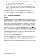
Note
Resistors and semiconductor junction in parallel with the diode
falsify the measured results!