
Datasheet
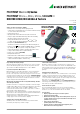

PROFITEST MTECH+, MPRO, MXTRA, SECULIFE IP
DIN VDE 0100/IEC 60364-6 Testers
10 GMC-I Messtechnik GmbH
Special Functions
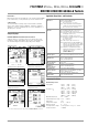
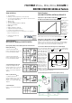
Voltage Drop Measurement (at Z
LN
) – ΔU Function
According to DIN VDE 100, part
600, voltage drop from the inter-
section of the distribution network
and the consumer system to the
point of connection of an electri-
cal power consumer (electrical
outlet or device connector termi-
nals) should not exceed 4% of
nominal line voltage.
Voltage drop calculation:
ΔU = Z
L-N
• rated fuse current
ΔU as % = ΔU / U
L-N
Measurement of the Impedance of Insulating Floors and Walls
(standing surface insulation impedance) – Z
ST
Function
The instrument measures the
impedance between a weighted
metal plate and earth. Line volt-
age available at the measuring
site is used as an alternating volt-
age source. The Z
ST
equivalent
circuit is considered a parallel cir-
cuit.
Special Functions PROFITEST MXTRA
Leakage Current Measurement with PRO-AB Adapter (PROFITEST MXTRA only)
Measurement of continuous leak-
age and patient auxiliary current
per IEC 62353 (VDE 0750, part 1)
/ IEC 601-1 / EN 60 601-1:2006
(Medical electrical equipment –
General requirements for basic
safety) is possible with the help of
the PRO-AB leakage current
measuring adapter used as an
accessory with the PROFITEST
MXTRA test instrument.
As specified in the standards
listed above, current values of up
to 10 mA may be measured with this measuring adapter.
In order to be able to fully cover
this measuring range using the
measurement input provided on
the test instrument (2-pole cur-
rent clamp input), the measuring
instrument is equipped with range
switching between transformation
ratios of 10:1 and 1:1.
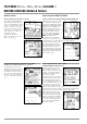
Testing of Insulation Monitoring Devices (IMDs)
(PROFITEST MXTRA and SECULIFE IP only)
Insulation monitors are used in
power supplies for which a sin-
gle-pole earth fault may not result
in failure of the power supply, for
example in operating rooms or
photovoltaic systems.
Insulation monitors can be tested
with the help of this special func-
tion. After pressing the start but-
ton, an adjustable insulation resis-
tance is activated between one of
the two phases of the IT system
to be monitored and ground to
this end. This resistance can be changed in the manual sequence
mode with the help of the softkeys, and it can be varied automat-
ically from R
max
to R
min
in the automatic operating mode.
Time, during which the momen-
tary resistance value prevails at
the system until the next change
in value, is displayed. The IMD’s
display and response characteris-
tics can be subsequently evalu-
ated and documented with the
help of the softkeys.