
Manual


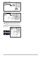


Table Of Contents
- 1 Safety Instructions
- 2 Applications
- 3 Documentation
- 4 Getting Started
- 5 The Instrument
- 6 Operating and Display Elements
- 7 Operation
- 8 Instrument Settings
- 9 Database
- 10 General Information on Measurements
- 10.1 Using Cable Sets and Test Probes
- 10.2 Test Plug – Changing Inserts
- 10.3 Connecting the Instrument
- 10.4 Automatic Settings, Monitoring and Shutdown
- 10.5 Measured Value Display and Memory
- 10.6 Help Function
- 10.7 Setting Parameters or Limit Values using RCD Measurement as an Example
- 10.8 Freely Selectable Parameter Settings or Limit Values
- 10.9 2-Pole Measurement with Rapid or Semiautomatic Polarity Reversal
- 11 Measuring Voltage and Frequency
- 12 Testing RCDs
- 12.1 Measuring Touch Voltage (with reference to nominal residual current) with ⅓ Nominal Residual Current and Tripping Test with Nominal Residual Current
- 12.2 Special Tests for Systems and RCDs
- 12.2.1 Testing Systems and RCCBs with Rising Residual Current (AC) for Type AC, A/F, B/B+ and EV/MI RCDs (PROFITEST MTECH+, PROFITEST MXTRA only)
- 12.2.2 Testing Systems and RCCBs with Rising Residual Current (AC) for Type B/B+ and EV/MI RCDs (PROFITEST MTECH+PROFITEST MXTRA)
- 12.2.3 Testing RCCBS with 5 × IDN
- 12.2.4 Testing of RCCBs which are Suitable for Pulsating DC Residual Current
- 12.3 Testing of Special RCDs
- 12.4 Testing Residual Current Circuit Breakers in TN-S Systems
- 12.5 Testing of RCD Protection in IT Systems with High Cable Capacitance (e.g. In Norway)
- 12.6 Testing of 6 mA Residual Current Devices RDC-DD/RCMB (RDC-DD: PROFITEST MXTRA and PROFITEST MTECH+ only)
- 13 Testing of Breaking Requirements for Overcurrent Protective Devices, Measurement of Loop Impedance and Determination of Short-Circuit Current (ZL-PE and ISC Functions)
- 14 Measuring Supply Impedance (ZL-N Function)
- 15 Earthing Resistance Measurement (Function RE)
- 15.1 Earthing Resistance Measurement – Mains Powered
- 15.2 Earthing Resistance Measurement – Battery Powered, “Battery Mode” (PROFITEST MPRO & PROFITEST MXTRA only)
- 15.3 Earthing Resistance, Mains Powered – 2-Pole Measurement with 2-Pole Adapter or Country-Specific Plug (Schuko) without Probe
- 15.4 Earthing Resistance Measurement. Mains Powered – 3-Pole Measurement: 2-Pole Adapter with Probe
- 15.5 Earthing Resistance Measurement, Mains Powered – Measuring Earth Electrode Potential (UE Function)
- 15.6 Earthing Resistance Measurement, Mains Powered – Selective Earthing Resistance Measurement with Current Clamp Sensor as Accessory
- 15.7 Earthing Resistance Measurement, Battery Powered, “Battery Mode” – 3-Pole (PROFITEST MPRO & PROFITEST MXTRA only)
- 15.8 Earthing Resistance Measurement, Battery Powered, “Battery Mode” – 4-Pole (PROFITEST MPRO & PROFITEST MXTRA only)
- 15.9 Earthing Resistance Measurement, Battery Powered, “Battery Mode” – Selective (4-pole) with Current Clamp Sensor and PRO-RE Measuring Adapter as Accessory (PROFITEST MPRO & PROFITEST MXTRA only)
- 15.10 Earthing Resistance Measurement, Battery Powered, “Battery Mode” – Ground Loop Measurement (with current clamp sensor and transformer, and pro-re measuring adapter as accessory) (PROFITEST MPRO & PROFITEST MXTRA only)
- 15.11 Earthing Resistance Measurement, Battery Powered, “Battery Mode” – Measurement of Soil Resistivity rE (PROFITEST MPRO & PROFITEST MXTRA only)
- 16 Measurement of Insulation Resistance
- 17 Measuring Low-Value Resistance of up to 200 W (Protective Conductor and Equipotential Bonding Conductor)
- 18 Measurement with Accessory Sensors
- 19 Special Functions – EXTRA Switch Position
- 19.1 Voltage Drop Measurement (at ZLN) – DU Function
- 19.2 Measuring the Impedance of Insulating Floors and Walls (standing surface insulation impedance) – ZST Function
- 19.3 Testing Meter Startup with Earthing Contact Plug – kWh Function
- 19.4 Leakage Current Measurement with PRO-AB Leakage Current Adapter as Accessory – IL Function (PROFITEST MXTRA only)
- 19.5 Testing Insulation Monitoring Devices – IMD Function (PROFITEST MXTRA only)
- 19.6 Residual Voltage Test – Ures Function (PROFITEST MXTRA only)
- 19.7 Intelligent Ramp – ta+ID Function (PROFITEST MXTRA only)
- 19.8 Testing Residual Current Monitors – RCM Function ( PROFITEST MXTRA only)
- 19.9 Checking the Operating Statuses of Electric Vehicles at Charging Stations per IEC 61851 ((PROFITEST MTECH+ & PROFITEST MXTRA)
- 19.10 PRCD – Test Sequences for Documenting Fault Simulations at PRCDs with the PROFITEST PRCD Adapter (PROFITEST MXTRA only)
- 20 Test Sequences (Automatic Test Sequences) – AUTO Function
- 21 Maintenance
- 22 Contact, Support and Service
- 23 CE Declaration
- 24 Disposal and Environmental Protection
- 25 Appendix
- 25.1 Tables for Determining Maximum and Minimum Display Values in Consideration of the Instrument’s Maximum Measuring and Intrinsic Uncertainties
- 25.2 At which values should/must an RCD actually be tripped? Requirements for Residual Current Devices (RCD)
- 25.3 Testing Electrical Machines per DIN EN 60 204 – Applications, Limit Values
- 25.4 Periodic Testing per DGUV V 3 (previously BGV A3) – Limit Values for Electrical Systems and Operating Equipment
- 25.5 Bibliography
- 25.6 Internet Addresses for Additional Information

60 Gossen Metrawatt GmbH
15.1 Earthing Resistance Measurement – Mains Powered
The following types of measurement and connection are possible:
• 2-wire measurement via 2-pole adapter
• 2-pole measurement via earthing contact plug
(not possible in IT systems)
• 3-wire measurement via 2-pole adapter and
probe
• Selective measurement: 2-pole measurement
with probe
and current clamp sensor
At left in figure:
2-pole measuring
adapter for con-
tacting PE and L
measuring points
At right in figure:
The PRO-Schuko
measuring
adapter can be
used as an alter-
native.
Select Measuring Function
Select Operating Mode
The selected operating mode is displayed inversely:
mains~ in white against a black background.
Special Case: Manual Measuring Range Selection (test current
selection)
(R AUTO, R = 10 k (4 mA), 1 k (40 mA), 100 (0,4 A),
10 (3.7 … 7 A), 10 /U
E
)
Note
When the measuring range is selected manually, accuracy val-
ues are only valid starting at 5% of the upper limit range value
(except for the 10 W range; separate display for small values).
Set Parameters
❏ Measuring range: AUTO
10 k (4 mA), 1 k (40 mA), 100 (0.4 A), 10 (> 3.7 A)
In systems with RCCBs, resistance or test current must be se-
lected such that it is less than tripping current (½ I
N
).
❏ Touch voltage: UL < 25 V, < 50 V, < 65 V, see section 10.8 re-
garding freely selectable voltage
❏ Transformer ratio: depends on utilized current clamp sensor
❏ Connection: 2-pole adapter, 2-pole adapter + probe,
2-pole adapter + clamp meter
❏ System type: TN or TT
❏ Test current waveform
See section 15.4 through section 15.6 regarding advisable
parameters for the respective measurement and connection
types.
Performing Measurements
See section 15.4 through section 15.6.
15.2 Earthing Resistance Measurement – Battery Powered,
“Battery Mode” (PROFITEST MPRO & PROFITEST MXTRA
only)
The 5 following types of measurement and connection are possi-
ble:
• 3-wire measurement via PRO-RE adapter
• 4-wire measurement via PRO-RE adapter
• Selective measurement with clamp meter (4-
pole)
via PRO-RE adapter
• 2-clamp measurement via PRO-RE/2 adapter
• Measurement of soil resistivity
E
via PRO-RE adapter
Figure at right:
PRO-RE adapter for connect-
ing earth electrode, auxiliary
earth electrode, probe and
auxiliary probe to the test
instrument for
3/4-pole measurement,
selective measurement and
measurement of soil resistivity
Figure at right:
PRO-RE/2 measuring adapter as
accessory for connecting the E-
Clip 2 generator clamp for 2-clamp
measurement and earth loop resis-
tance measurement.
Select Measuring Function
Select Operating Mode
The selected operating mode is displayed inversely:
white battery icon against black background.
Set Parameters
❏ Measuring range: AUTO, 50 k, 20 kW, 2 kW, 200 W, 20 W
❏ Current clamp sensor transformer ratio:
1:1 (1 V/A,) 1:10 (100 mV/A), 1:100 (10 mV/A), 1:1000 (1 mV/A)
❏ Connection: 3-pole, 4-pole, selective, 2-clamp,
E
(Rho)
❏ Distance d (for measuring
E
): xx m
See section 15.7 through section 15.11 regarding advisable
parameters for the respective measurement and connection
types.
Performing Measurements
See section 15.7 through section 15.11.
R
E
R
E