
Manual


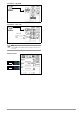


Table Of Contents
- 1 Safety Instructions
- 2 Applications
- 3 Documentation
- 4 Getting Started
- 5 The Instrument
- 6 Operating and Display Elements
- 7 Operation
- 8 Instrument Settings
- 9 Database
- 10 General Information on Measurements
- 10.1 Using Cable Sets and Test Probes
- 10.2 Test Plug – Changing Inserts
- 10.3 Connecting the Instrument
- 10.4 Automatic Settings, Monitoring and Shutdown
- 10.5 Measured Value Display and Memory
- 10.6 Help Function
- 10.7 Setting Parameters or Limit Values using RCD Measurement as an Example
- 10.8 Freely Selectable Parameter Settings or Limit Values
- 10.9 2-Pole Measurement with Rapid or Semiautomatic Polarity Reversal
- 11 Measuring Voltage and Frequency
- 12 Testing RCDs
- 12.1 Measuring Touch Voltage (with reference to nominal residual current) with ⅓ Nominal Residual Current and Tripping Test with Nominal Residual Current
- 12.2 Special Tests for Systems and RCDs
- 12.2.1 Testing Systems and RCCBs with Rising Residual Current (AC) for Type AC, A/F, B/B+ and EV/MI RCDs (PROFITEST MTECH+, PROFITEST MXTRA only)
- 12.2.2 Testing Systems and RCCBs with Rising Residual Current (AC) for Type B/B+ and EV/MI RCDs (PROFITEST MTECH+PROFITEST MXTRA)
- 12.2.3 Testing RCCBS with 5 × IDN
- 12.2.4 Testing of RCCBs which are Suitable for Pulsating DC Residual Current
- 12.3 Testing of Special RCDs
- 12.4 Testing Residual Current Circuit Breakers in TN-S Systems
- 12.5 Testing of RCD Protection in IT Systems with High Cable Capacitance (e.g. In Norway)
- 12.6 Testing of 6 mA Residual Current Devices RDC-DD/RCMB (RDC-DD: PROFITEST MXTRA and PROFITEST MTECH+ only)
- 13 Testing of Breaking Requirements for Overcurrent Protective Devices, Measurement of Loop Impedance and Determination of Short-Circuit Current (ZL-PE and ISC Functions)
- 14 Measuring Supply Impedance (ZL-N Function)
- 15 Earthing Resistance Measurement (Function RE)
- 15.1 Earthing Resistance Measurement – Mains Powered
- 15.2 Earthing Resistance Measurement – Battery Powered, “Battery Mode” (PROFITEST MPRO & PROFITEST MXTRA only)
- 15.3 Earthing Resistance, Mains Powered – 2-Pole Measurement with 2-Pole Adapter or Country-Specific Plug (Schuko) without Probe
- 15.4 Earthing Resistance Measurement. Mains Powered – 3-Pole Measurement: 2-Pole Adapter with Probe
- 15.5 Earthing Resistance Measurement, Mains Powered – Measuring Earth Electrode Potential (UE Function)
- 15.6 Earthing Resistance Measurement, Mains Powered – Selective Earthing Resistance Measurement with Current Clamp Sensor as Accessory
- 15.7 Earthing Resistance Measurement, Battery Powered, “Battery Mode” – 3-Pole (PROFITEST MPRO & PROFITEST MXTRA only)
- 15.8 Earthing Resistance Measurement, Battery Powered, “Battery Mode” – 4-Pole (PROFITEST MPRO & PROFITEST MXTRA only)
- 15.9 Earthing Resistance Measurement, Battery Powered, “Battery Mode” – Selective (4-pole) with Current Clamp Sensor and PRO-RE Measuring Adapter as Accessory (PROFITEST MPRO & PROFITEST MXTRA only)
- 15.10 Earthing Resistance Measurement, Battery Powered, “Battery Mode” – Ground Loop Measurement (with current clamp sensor and transformer, and pro-re measuring adapter as accessory) (PROFITEST MPRO & PROFITEST MXTRA only)
- 15.11 Earthing Resistance Measurement, Battery Powered, “Battery Mode” – Measurement of Soil Resistivity rE (PROFITEST MPRO & PROFITEST MXTRA only)
- 16 Measurement of Insulation Resistance
- 17 Measuring Low-Value Resistance of up to 200 W (Protective Conductor and Equipotential Bonding Conductor)
- 18 Measurement with Accessory Sensors
- 19 Special Functions – EXTRA Switch Position
- 19.1 Voltage Drop Measurement (at ZLN) – DU Function
- 19.2 Measuring the Impedance of Insulating Floors and Walls (standing surface insulation impedance) – ZST Function
- 19.3 Testing Meter Startup with Earthing Contact Plug – kWh Function
- 19.4 Leakage Current Measurement with PRO-AB Leakage Current Adapter as Accessory – IL Function (PROFITEST MXTRA only)
- 19.5 Testing Insulation Monitoring Devices – IMD Function (PROFITEST MXTRA only)
- 19.6 Residual Voltage Test – Ures Function (PROFITEST MXTRA only)
- 19.7 Intelligent Ramp – ta+ID Function (PROFITEST MXTRA only)
- 19.8 Testing Residual Current Monitors – RCM Function ( PROFITEST MXTRA only)
- 19.9 Checking the Operating Statuses of Electric Vehicles at Charging Stations per IEC 61851 ((PROFITEST MTECH+ & PROFITEST MXTRA)
- 19.10 PRCD – Test Sequences for Documenting Fault Simulations at PRCDs with the PROFITEST PRCD Adapter (PROFITEST MXTRA only)
- 20 Test Sequences (Automatic Test Sequences) – AUTO Function
- 21 Maintenance
- 22 Contact, Support and Service
- 23 CE Declaration
- 24 Disposal and Environmental Protection
- 25 Appendix
- 25.1 Tables for Determining Maximum and Minimum Display Values in Consideration of the Instrument’s Maximum Measuring and Intrinsic Uncertainties
- 25.2 At which values should/must an RCD actually be tripped? Requirements for Residual Current Devices (RCD)
- 25.3 Testing Electrical Machines per DIN EN 60 204 – Applications, Limit Values
- 25.4 Periodic Testing per DGUV V 3 (previously BGV A3) – Limit Values for Electrical Systems and Operating Equipment
- 25.5 Bibliography
- 25.6 Internet Addresses for Additional Information

Gossen Metrawatt GmbH 59
15 Earthing Resistance Measurement (Function R
E
)
Earthing resistance R
E
is important for automatic shutdown in
system segments. It must have a low value in order to assure that
high short-circuit current flows and the system is shut down reli-
ably by the RCCB in the event of a fault.
Test Setup
Earthing resistance (R
E
) is the sum of the earth electrode’s dissi-
pation resistance and earth conductor resistance. Earthing resis-
tance is measured by applying an alternating current via the earth
conductor, the earth electrode and dissipation resistance. This
current, as well as voltage between the earth electrode and a
probe, are measured.
The probe is connected to the probe connector socket (17) with a
4 mm contact protected plug.
Direct measurement with probe (mains powered earthing mea-
surement)
Direct measurement of earthing resistance R
E
is only possible
within a measuring circuit which includes a probe. However, this
means that the probe and reference earth must be of like poten-
tial, i.e. that they are positioned outside of the potential gradient
area. The distance between the earth electrode and the probe
should be at least 20 m.
Measurement without probe (mains powered earthing measure-
ment)
In many cases, especially in extremely built-up areas, it’s difficult,
or even impossible, to set a measuring probe. In such cases,
earthing resistance can be measured without a probe. In this
case, however, the resistance values for the operational earth
electrode R
B
and phase conductor L are also included in the
measurement results.
Measuring method (with probe) (mains powered earthing mea-
surement)
The instrument measures earthing resistance R
E
by means of the
ammeter-voltmeter test.
Resistance R
E
is calculated from the quotient of voltage U
E
and
current I
E
where U
E
is between the earth electrode and the probe.
The test current which is applied to earthing resistance is con-
trolled by the instrument (see section 5.5, “Technical Data”, on
page 10 for pertinent values).
A voltage drop is generated which is proportional to earthing
resistance.
Note
Measurement cable and measuring adapter resistance
are compensated automatically during measurement and
have no effect on measurement results.
If dangerous touch voltages occur during measurement
(> 50 V), the measurement is interrupted and safety shut-
down occurs.
Probe resistance does not affect measurement results
and may be as high as 50 k.
Attention!
!
The probe is part of the measuring circuit and may carry
a current of up to 3.5 mA in accordance with IEC 61557
/ EN 61557.
Measurement with or without earth electrode voltage depending
upon entered parameters and the selected type of connection:
* This parameter results in automatic selection of probe connection.
Measuring method with suppression of RCD tripping
(mains powered earthing measurement) (PROFITEST MTECH+,
PROFITEST MXTRA only)
The test instrument makes it possible to measure earthing resis-
tance in TN systems with type A , F and AC
RCCBs
(10, 30, 100, 300, 500 mA nominal residual current).
The test instrument
generates a direct
current to this end,
which saturates the
RCCB’s magnetic
circuit.
The test instrument
then superimposes
a measuring current
which only demon-
strates half-waves
of like polarity. The
RCCB is no longer
capable of detect-
ing this measuring
current, and is con-
sequently not
tripped during measurement.
A four conductor measuring cable is used between the instru-
ment and the test plug. Cable and measuring adapter resistance
is automatically compensated during measurement and does not
affect measurement results.
Note
Bias Magnetization
Only AC measurements can be performed with the 2-
pole adapter. Suppression of RCD tripping by means of
bias magnetization with direct current is only possible via
a country-specific plug insert, e.g. SCHUKO, or the 3-
pole adapter (neutral conductor N required).
Limit Values
Earthing resistance (earth coupling resistance) is determined pri-
marily by the electrode’s contact surface and the conductivity of
the surrounding earth.
The specified limit value depends on the type of electrical system
and its shutdown conditions in consideration of maximum touch
voltage.
Evaluating Measured Values
The maximum permissible displayed resistance values which
assure that the required earthing resistance is not exceeded, and
for which maximum device operating error has already been
taken into consideration (at nominal conditions of use), can be
determined with the help of Table 2 on page 100. Intermediate
values can be interpolated.
RANGE Connection Measuring
Functions
xx / xx k
No probe measurement
No U
E
measurement
10 / U
E
*
Probe measurement
activated
U
E
is measured
xx / xx k *
Probe measurement
activated
No U
E
measurement
Clamp measurement
activated
No U
E
measurement
Start
t1
t3
Measure
t2
Operation
RCD Disabled!
t
I
F
/mA
Suppression of RCCB tripping for
RCCBs which are sensitive to pulsed
current