
Manual


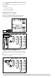
Table Of Contents
- 1 Safety Instructions
- 2 Applications
- 3 Documentation
- 4 Getting Started
- 5 The Instrument
- 6 Operating and Display Elements
- 7 Operation
- 8 Instrument Settings
- 9 Database
- 10 General Information on Measurements
- 10.1 Using Cable Sets and Test Probes
- 10.2 Test Plug – Changing Inserts
- 10.3 Connecting the Instrument
- 10.4 Automatic Settings, Monitoring and Shutdown
- 10.5 Measured Value Display and Memory
- 10.6 Help Function
- 10.7 Setting Parameters or Limit Values using RCD Measurement as an Example
- 10.8 Freely Selectable Parameter Settings or Limit Values
- 10.9 2-Pole Measurement with Rapid or Semiautomatic Polarity Reversal
- 11 Measuring Voltage and Frequency
- 12 Testing RCDs
- 12.1 Measuring Touch Voltage (with reference to nominal residual current) with ⅓ Nominal Residual Current and Tripping Test with Nominal Residual Current
- 12.2 Special Tests for Systems and RCDs
- 12.2.1 Testing Systems and RCCBs with Rising Residual Current (AC) for Type AC, A/F, B/B+ and EV/MI RCDs (PROFITEST MTECH+, PROFITEST MXTRA only)
- 12.2.2 Testing Systems and RCCBs with Rising Residual Current (AC) for Type B/B+ and EV/MI RCDs (PROFITEST MTECH+PROFITEST MXTRA)
- 12.2.3 Testing RCCBS with 5 × IDN
- 12.2.4 Testing of RCCBs which are Suitable for Pulsating DC Residual Current
- 12.3 Testing of Special RCDs
- 12.4 Testing Residual Current Circuit Breakers in TN-S Systems
- 12.5 Testing of RCD Protection in IT Systems with High Cable Capacitance (e.g. In Norway)
- 12.6 Testing of 6 mA Residual Current Devices RDC-DD/RCMB (RDC-DD: PROFITEST MXTRA and PROFITEST MTECH+ only)
- 13 Testing of Breaking Requirements for Overcurrent Protective Devices, Measurement of Loop Impedance and Determination of Short-Circuit Current (ZL-PE and ISC Functions)
- 14 Measuring Supply Impedance (ZL-N Function)
- 15 Earthing Resistance Measurement (Function RE)
- 15.1 Earthing Resistance Measurement – Mains Powered
- 15.2 Earthing Resistance Measurement – Battery Powered, “Battery Mode” (PROFITEST MPRO & PROFITEST MXTRA only)
- 15.3 Earthing Resistance, Mains Powered – 2-Pole Measurement with 2-Pole Adapter or Country-Specific Plug (Schuko) without Probe
- 15.4 Earthing Resistance Measurement. Mains Powered – 3-Pole Measurement: 2-Pole Adapter with Probe
- 15.5 Earthing Resistance Measurement, Mains Powered – Measuring Earth Electrode Potential (UE Function)
- 15.6 Earthing Resistance Measurement, Mains Powered – Selective Earthing Resistance Measurement with Current Clamp Sensor as Accessory
- 15.7 Earthing Resistance Measurement, Battery Powered, “Battery Mode” – 3-Pole (PROFITEST MPRO & PROFITEST MXTRA only)
- 15.8 Earthing Resistance Measurement, Battery Powered, “Battery Mode” – 4-Pole (PROFITEST MPRO & PROFITEST MXTRA only)
- 15.9 Earthing Resistance Measurement, Battery Powered, “Battery Mode” – Selective (4-pole) with Current Clamp Sensor and PRO-RE Measuring Adapter as Accessory (PROFITEST MPRO & PROFITEST MXTRA only)
- 15.10 Earthing Resistance Measurement, Battery Powered, “Battery Mode” – Ground Loop Measurement (with current clamp sensor and transformer, and pro-re measuring adapter as accessory) (PROFITEST MPRO & PROFITEST MXTRA only)
- 15.11 Earthing Resistance Measurement, Battery Powered, “Battery Mode” – Measurement of Soil Resistivity rE (PROFITEST MPRO & PROFITEST MXTRA only)
- 16 Measurement of Insulation Resistance
- 17 Measuring Low-Value Resistance of up to 200 W (Protective Conductor and Equipotential Bonding Conductor)
- 18 Measurement with Accessory Sensors
- 19 Special Functions – EXTRA Switch Position
- 19.1 Voltage Drop Measurement (at ZLN) – DU Function
- 19.2 Measuring the Impedance of Insulating Floors and Walls (standing surface insulation impedance) – ZST Function
- 19.3 Testing Meter Startup with Earthing Contact Plug – kWh Function
- 19.4 Leakage Current Measurement with PRO-AB Leakage Current Adapter as Accessory – IL Function (PROFITEST MXTRA only)
- 19.5 Testing Insulation Monitoring Devices – IMD Function (PROFITEST MXTRA only)
- 19.6 Residual Voltage Test – Ures Function (PROFITEST MXTRA only)
- 19.7 Intelligent Ramp – ta+ID Function (PROFITEST MXTRA only)
- 19.8 Testing Residual Current Monitors – RCM Function ( PROFITEST MXTRA only)
- 19.9 Checking the Operating Statuses of Electric Vehicles at Charging Stations per IEC 61851 ((PROFITEST MTECH+ & PROFITEST MXTRA)
- 19.10 PRCD – Test Sequences for Documenting Fault Simulations at PRCDs with the PROFITEST PRCD Adapter (PROFITEST MXTRA only)
- 20 Test Sequences (Automatic Test Sequences) – AUTO Function
- 21 Maintenance
- 22 Contact, Support and Service
- 23 CE Declaration
- 24 Disposal and Environmental Protection
- 25 Appendix
- 25.1 Tables for Determining Maximum and Minimum Display Values in Consideration of the Instrument’s Maximum Measuring and Intrinsic Uncertainties
- 25.2 At which values should/must an RCD actually be tripped? Requirements for Residual Current Devices (RCD)
- 25.3 Testing Electrical Machines per DIN EN 60 204 – Applications, Limit Values
- 25.4 Periodic Testing per DGUV V 3 (previously BGV A3) – Limit Values for Electrical Systems and Operating Equipment
- 25.5 Bibliography
- 25.6 Internet Addresses for Additional Information

Gossen Metrawatt GmbH 33
9.3.1 Creating Structures (example for electrical circuit)
After selection with the MEM key, all setting options for the cre-
ation of a tree structure are made available on three menu pages
(1/3, 2/3 and 3/3). The tree structure consists of structure ele-
ments, referred to below as objects.
Selecting the Position at which a New Object will be Added
Use the keys in order to select structure elements.
Change to the sub-level with the key.
Go to the next page with the >> key
Creating a New Object
Press the key in order to create a new object.
Select a new object from a list.
Select the desired object from the list with the keys and
acknowledge with the key.
Depending upon the profile selected in the test instrument’s
SETUP menu (see section 8), the number of object types may be
limited, and the hierarchy may be laid out differently.
Entering a Designation
Enter a designation and then acknowledge it with ✓.
Note
Acknowledge your entry with ✓and , because the entry
will otherwise not be accepted.
Entering a Comment
Enter a comment and then acknowledge it with ✓.
Note
Acknowledge your entry with ✓ and , because the entry
will otherwise not be accepted.
Setting Electrical Circuit Parameters
For example, nominal current values must be entered here for the
selected electrical circuit. Measuring parameters which have been
accepted and saved in this way are subsequently accepted by
the current measuring menu automatically when the display is
switched from the structure view to measurement.
Note
Electrical circuit parameters changed during structure
creation are also retained for individual measurements
(measurement without saving data).
If you change the electrical circuit parameters specified by the
structure in the test instrument, a warning is displayed when
the change is saved (see error message on page 25).
Scroll up
Scroll down
Comfirm selection /
Display object
Nextpage
change level
or ID number
Create object
Delete object
VA: Show measurement data
Edit designation
Scroll up
Scroll down
Comfirm selection
Select character
Select character
Accept character
Delete character
Character selection:
✓Save object designation
A, a, 0, @
Select parameter
Parameter settings list
Acknowledge parameter selection
Acknowledge parameter setting
and return to page 1/3
Select parameter setting
in the database menu.