
Manual

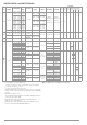


Table Of Contents
- 1 Safety Instructions
- 2 Applications
- 3 Documentation
- 4 Getting Started
- 5 The Instrument
- 6 Operating and Display Elements
- 7 Operation
- 8 Instrument Settings
- 9 Database
- 10 General Information on Measurements
- 10.1 Using Cable Sets and Test Probes
- 10.2 Test Plug – Changing Inserts
- 10.3 Connecting the Instrument
- 10.4 Automatic Settings, Monitoring and Shutdown
- 10.5 Measured Value Display and Memory
- 10.6 Help Function
- 10.7 Setting Parameters or Limit Values using RCD Measurement as an Example
- 10.8 Freely Selectable Parameter Settings or Limit Values
- 10.9 2-Pole Measurement with Rapid or Semiautomatic Polarity Reversal
- 11 Measuring Voltage and Frequency
- 12 Testing RCDs
- 12.1 Measuring Touch Voltage (with reference to nominal residual current) with ⅓ Nominal Residual Current and Tripping Test with Nominal Residual Current
- 12.2 Special Tests for Systems and RCDs
- 12.2.1 Testing Systems and RCCBs with Rising Residual Current (AC) for Type AC, A/F, B/B+ and EV/MI RCDs (PROFITEST MTECH+, PROFITEST MXTRA only)
- 12.2.2 Testing Systems and RCCBs with Rising Residual Current (AC) for Type B/B+ and EV/MI RCDs (PROFITEST MTECH+PROFITEST MXTRA)
- 12.2.3 Testing RCCBS with 5 × IDN
- 12.2.4 Testing of RCCBs which are Suitable for Pulsating DC Residual Current
- 12.3 Testing of Special RCDs
- 12.4 Testing Residual Current Circuit Breakers in TN-S Systems
- 12.5 Testing of RCD Protection in IT Systems with High Cable Capacitance (e.g. In Norway)
- 12.6 Testing of 6 mA Residual Current Devices RDC-DD/RCMB (RDC-DD: PROFITEST MXTRA and PROFITEST MTECH+ only)
- 13 Testing of Breaking Requirements for Overcurrent Protective Devices, Measurement of Loop Impedance and Determination of Short-Circuit Current (ZL-PE and ISC Functions)
- 14 Measuring Supply Impedance (ZL-N Function)
- 15 Earthing Resistance Measurement (Function RE)
- 15.1 Earthing Resistance Measurement – Mains Powered
- 15.2 Earthing Resistance Measurement – Battery Powered, “Battery Mode” (PROFITEST MPRO & PROFITEST MXTRA only)
- 15.3 Earthing Resistance, Mains Powered – 2-Pole Measurement with 2-Pole Adapter or Country-Specific Plug (Schuko) without Probe
- 15.4 Earthing Resistance Measurement. Mains Powered – 3-Pole Measurement: 2-Pole Adapter with Probe
- 15.5 Earthing Resistance Measurement, Mains Powered – Measuring Earth Electrode Potential (UE Function)
- 15.6 Earthing Resistance Measurement, Mains Powered – Selective Earthing Resistance Measurement with Current Clamp Sensor as Accessory
- 15.7 Earthing Resistance Measurement, Battery Powered, “Battery Mode” – 3-Pole (PROFITEST MPRO & PROFITEST MXTRA only)
- 15.8 Earthing Resistance Measurement, Battery Powered, “Battery Mode” – 4-Pole (PROFITEST MPRO & PROFITEST MXTRA only)
- 15.9 Earthing Resistance Measurement, Battery Powered, “Battery Mode” – Selective (4-pole) with Current Clamp Sensor and PRO-RE Measuring Adapter as Accessory (PROFITEST MPRO & PROFITEST MXTRA only)
- 15.10 Earthing Resistance Measurement, Battery Powered, “Battery Mode” – Ground Loop Measurement (with current clamp sensor and transformer, and pro-re measuring adapter as accessory) (PROFITEST MPRO & PROFITEST MXTRA only)
- 15.11 Earthing Resistance Measurement, Battery Powered, “Battery Mode” – Measurement of Soil Resistivity rE (PROFITEST MPRO & PROFITEST MXTRA only)
- 16 Measurement of Insulation Resistance
- 17 Measuring Low-Value Resistance of up to 200 W (Protective Conductor and Equipotential Bonding Conductor)
- 18 Measurement with Accessory Sensors
- 19 Special Functions – EXTRA Switch Position
- 19.1 Voltage Drop Measurement (at ZLN) – DU Function
- 19.2 Measuring the Impedance of Insulating Floors and Walls (standing surface insulation impedance) – ZST Function
- 19.3 Testing Meter Startup with Earthing Contact Plug – kWh Function
- 19.4 Leakage Current Measurement with PRO-AB Leakage Current Adapter as Accessory – IL Function (PROFITEST MXTRA only)
- 19.5 Testing Insulation Monitoring Devices – IMD Function (PROFITEST MXTRA only)
- 19.6 Residual Voltage Test – Ures Function (PROFITEST MXTRA only)
- 19.7 Intelligent Ramp – ta+ID Function (PROFITEST MXTRA only)
- 19.8 Testing Residual Current Monitors – RCM Function ( PROFITEST MXTRA only)
- 19.9 Checking the Operating Statuses of Electric Vehicles at Charging Stations per IEC 61851 ((PROFITEST MTECH+ & PROFITEST MXTRA)
- 19.10 PRCD – Test Sequences for Documenting Fault Simulations at PRCDs with the PROFITEST PRCD Adapter (PROFITEST MXTRA only)
- 20 Test Sequences (Automatic Test Sequences) – AUTO Function
- 21 Maintenance
- 22 Contact, Support and Service
- 23 CE Declaration
- 24 Disposal and Environmental Protection
- 25 Appendix
- 25.1 Tables for Determining Maximum and Minimum Display Values in Consideration of the Instrument’s Maximum Measuring and Intrinsic Uncertainties
- 25.2 At which values should/must an RCD actually be tripped? Requirements for Residual Current Devices (RCD)
- 25.3 Testing Electrical Machines per DIN EN 60 204 – Applications, Limit Values
- 25.4 Periodic Testing per DGUV V 3 (previously BGV A3) – Limit Values for Electrical Systems and Operating Equipment
- 25.5 Bibliography
- 25.6 Internet Addresses for Additional Information

Gossen Metrawatt GmbH 11
5.6 Characteristic Values for PROFITEST MTECH+ and PROFITEST MBASE+
Func-
tion
Measured
Quantity
Display Range
Reso-
lution
Input
Impedance /
Test Current
Measuring Range
Nominal Val-
ues
Measuring Un-
certainty
Intrinsic
Uncertainty
Connections
Plug
Insert
1
2-Pole
Adapter
3-Pole
Adapter
Probe
Clamp Meters
WZ12C Z3512A
MFLEX
P300
U
U
L-PE
U
N-PE
0 … 99.9 V 0.1 V
5M
0.3 … 600 V
1
U
N
= 120, 230,
400, 500 V
f
N
= 16.7, 50,
60, 200, 400 Hz
±(|2% rdg.|+5d) ±(|1% rdg.|+5d)
100 … 600 V 1 V ±(|2% rdg.|+1d) ±(|1% rdg.|+1d)
f
15.0 … 99.9 Hz
100 … 999 Hz
0.1 Hz
1 Hz
DC
15.4 … 420 Hz
±(|0.2% rdg.|+1d) ±(|0.1% rdg.|+1d)
U
3 AC
0V … 99.9V
100 V … 600 V
0.1 V
1V
0.3 V … 600 V
±(|3% rdg.|+5d)
±(|3% rdg.|+1d)
±(|2% rdg.|+5d)
±(|2% rdg.|+1d)
U
Probe
0 … 99.9 V
100 … 600 V
0.1 V
1V
1.0 V … 600 V
±(|2% rdg.|+5d)
±(|2% rdg.|+1d)
±(|1% rdg.|+5d)
±(|1% rdg.|+1d)
U
L-N
0 … 99.9 V
100 … 600 V
0.1 V
1V
1.0 … 600 V
1
±(|3% rdg.|+5d)
±(|3% rdg.|+1d)
±(|2% rdg.|+5d)
±(|2% rdg.|+1d)
I
I
F
U
IN
0 … 70.0 V 0.1 V 0.3 × I
N
5 V … 70 V
U
N
=
120 V,
230 V,
400 V
2
f
N
= 50 Hz,
60 Hz
U
L
= 25 V, 50 V
I
N
=
6 mA,
10 mA,
30 mA,
100 mA,
300 mA,
500 mA
2
+|10% rdg.|+1d
+|1% rdg.|–1d …
+|9% rdg.|+1d
option
ally
R
E
10 … 999
1.00 k … 6.51 k
1
0.01 k
I
N
= 10 mA × 1.05
Calculated value
from
R
E
= U
IN
/
I
N
3 … 999
1 k … 2.17 k
1
0.01 k
I
N
= 30 mA × 1.05
1 … 651 1
I
N
= 100 mA × 1.05
0.3 … 99.9
100 … 217
0.1
1
I
N
= 300 mA × 1.05
0.2 … 9.9
10 … 130
0.1
1
I
N
= 500 mA × 1.05
I
F
(I
N
= 6 mA) 1.8 … 7.8 mA
0.1 mA
1.8 … 7.8 mA 1.8 … 7.8 mA
±(|5% rdg.|+1d)
±(|3.5% rdg.|+2d)
I
F
(I
N
= 10 mA) 3.0 … 13.0 mA 3.0 … 13.0 mA 3.0 … 13.0 mA
I
F
(I
N
= 30 mA) 9.0 … 39.0 mA 9.0 … 39.0 mA 9.0 … 39.0 mA
I
F
(I
N
= 100 mA) 30 … 130 mA 1 mA 30 … 130 mA 30 … 130 mA
I
F
(I
N
= 300 mA) 90 … 390 mA 1 mA 90 … 390 mA 90 … 390 mA
I
F
(I
N
= 500 mA) 150 … 650 mA 1 mA 150 … 650 mA 150 … 650 mA
U
I
/ U
L
= 25 V 0 … 25.0 V
0.1 V Same as I
0 … 25.0 V
+|10% rdg.|+1d
+|1% rdg.|–1d …
+|9% rdg.|+1d
U
I
/ U
L
= 50 V 0 … 50.0 V 0 … 50.0 V
t
A
(I
N
× 1) 0 … 1000 ms 1ms 6 … 500 mA 0 … 1000 ms
4 ms 3 ms
t
A
(I
N
× 2) 0 … 1000 ms 1ms
2 × 6 mA …
2 × 500 mA
0 … 1000 ms
t
A
(I
N
× 5) 0 … 40 ms 1ms
5 × 6 mA …
5 × 300 mA
0 … 40 ms
Z
L-PE
Z
L-N
Z
L-PE
()
Z
L-N
0 m … 999 m
1.00 … 9.99
1 m
0.01
0.1
1.3 A AC …
3.7 A AC
0.5A DC,
1.25 A DC
8
0.15 … 0.49
0.50 … 0.99
1.00 … 9.99
U
N
= 120 V,
230, 400,
500 V
1
f
N
=16.7 Hz, 50 Hz,
60 Hz
±(|10% rdg.|+30d)
±(|10% rdg.|+30d)
±(|5% rdg.|+3d)
±(|5% rdg.|+30d)
±(|4% rdg.|+30d)
±(|3% rdg.|+3d)
Z
L-PE
Z
L-PE
+ DC
8
0 m… 999 m
1.00 … 9.99
10.0 … 29.9
0.25 … 0.99
1.00 … 9.99
U
N
= 120, 230 V
f
N
= 50, 60 Hz
±(|18% rdg.|+30d)
±(|10% rdg.|+3d)
±(|6% rdg.|+50d)
±(|4% rdg.|+3d)
I
SC
(Z
L-PE
,
ZL-PE
+ DC)
8
0 to 9.9 A
10 … 999 A
1.00 … 9.99 kA
10.0 … 50.0 kA
0.1 A
1A
10 A
100 A
120 (108 … 132) V
230 (196 … 253) V
400 (340 … 440) V
500 (450 … 550) V
Value calculated from Z
L-PE
Z
L-PE
(15 mA)
0.6 … 9.9 0.1 Display range only
10.0 … 99.9
100 … 999
0.1
1
15 mA AC
10.0 … 99.9
100 … 999
U
N
= 120, 230 V
f
N
= 16.7
8
, 50,
60 Hz
±(|10% rdg.|+10d)
±(|8% rdg.|+2d)
±(|2% rdg.|+2d)
±(|1% rdg.|+1d)
I
SC
(15 mA)
100 … 999 mA
0.00 … 9.99 A
10.0 … 99.9 A
1mA
0.01 A
0.1 A
Calculated value
depending on U
N
and
Z
L-PE
:
I
SC
=
U
N
/10 …1000
Value calculated from Z
L-PE
(15 mA):
I
SC
= U
N
/Z
L-P E
(15 mA)
R
E
R
E
(with probe)
[R
E
(without probe)
values same as
Z
L-PE
]
0 m … 999 m
1.00 … 9.99
10.0 … 99.9
100 … 999
1 k …9.99 k
1 m
0.01
0.1
1
0.01 k
1.3 … 3.7 A AC
1.3 … 3.7 A AC
1.3 … 3.7 A AC
400 mA AC
40 mA AC
4 mA AC
0.15 … 0.49
0.50 … 0.99
1.0 …9.99
10 …99.9
100 …999
1 k …9.99 k
U
N
= 120, 230 V
U
N
= 400 V
1
f
N
= 50, 60 Hz
±(|10% rdg.|+30d)
±(|10% rdg.|+30d)
±(|5% rdg.|+3d)
±(|10% rdg.|+3d)
±(|10% rdg.|+3d)
±(|10% rdg.|+3d)
±(|5% rdg.|+30d)
±(|4% rdg.|+30d)
±(|3% rdg.|+3d)
±(|3% rdg.|+3d)
±(|3% rdg.|+3d)
±(|3% rdg.|+3d)
R
E
DC+
8
0 m … 999 m
1.00 … 9.99
10.0 … 29.9
1 m
0.01
0.1
1.3 … 3.7 A AC
0.5, 1.25 A DC
8
0.25 … 0.99
1.00 … 9.99
U
N
= 120, 230 V
f
N
= 50, 60 Hz
±(|18% rdg.|+30d)
±(|10% rdg.|+3d)
±(|6% rdg.|+50d)
±(|4% rdg.|+3d)
U
E
0 … 253 V 1 V — Calculated value
R
E
Sel
Clamp
R
E
0 … 999
1 m…
1
1.3 … 2.7 A AC
0.5 / 1.25 A DC
8
0.25 … 300
4
See R
E
±(|20% rdg.|+20d) ±(|15% rdg.|+20d)
R
E
DC+
8
0 … 999
1 m…
1
U
N
= 120, 230 V
f
N
= 50, 60 Hz
±(|22% rdg.|+20d) ±(|15% rdg.|+20d)
EXTRA
Z
ST
10 k … 199 k
1 k
1 k
0.01 M
0.1 M
2.3 mA at 230 V
10 k … 199 k
U
0
= U
L-N
±(|20% rdg.|+2d) ±(|10% rdg.|+3d)
200 k … 999 k
1.00 M
… 9.99 M
10.0 M
… 30.0 M
200 k … 999 k
1.00 M
… 9.99 M
10.0 M
… 30.0 M
±(|10% rdg.|+2d) ±(|5% rdg.|+3d)