
Manual


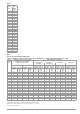


Table Of Contents
- 1 Safety Instructions
- 2 Applications
- 3 Documentation
- 4 Getting Started
- 5 The Instrument
- 6 Operating and Display Elements
- 7 Operation
- 8 Instrument Settings
- 9 Database
- 10 General Information on Measurements
- 10.1 Using Cable Sets and Test Probes
- 10.2 Test Plug – Changing Inserts
- 10.3 Connecting the Instrument
- 10.4 Automatic Settings, Monitoring and Shutdown
- 10.5 Measured Value Display and Memory
- 10.6 Help Function
- 10.7 Setting Parameters or Limit Values using RCD Measurement as an Example
- 10.8 Freely Selectable Parameter Settings or Limit Values
- 10.9 2-Pole Measurement with Rapid or Semiautomatic Polarity Reversal
- 11 Measuring Voltage and Frequency
- 12 Testing RCDs
- 12.1 Measuring Touch Voltage (with reference to nominal residual current) with ⅓ Nominal Residual Current and Tripping Test with Nominal Residual Current
- 12.2 Special Tests for Systems and RCDs
- 12.2.1 Testing Systems and RCCBs with Rising Residual Current (AC) for Type AC, A/F, B/B+ and EV/MI RCDs (PROFITEST MTECH+, PROFITEST MXTRA only)
- 12.2.2 Testing Systems and RCCBs with Rising Residual Current (AC) for Type B/B+ and EV/MI RCDs (PROFITEST MTECH+PROFITEST MXTRA)
- 12.2.3 Testing RCCBS with 5 × IDN
- 12.2.4 Testing of RCCBs which are Suitable for Pulsating DC Residual Current
- 12.3 Testing of Special RCDs
- 12.4 Testing Residual Current Circuit Breakers in TN-S Systems
- 12.5 Testing of RCD Protection in IT Systems with High Cable Capacitance (e.g. In Norway)
- 12.6 Testing of 6 mA Residual Current Devices RDC-DD/RCMB (RDC-DD: PROFITEST MXTRA and PROFITEST MTECH+ only)
- 13 Testing of Breaking Requirements for Overcurrent Protective Devices, Measurement of Loop Impedance and Determination of Short-Circuit Current (ZL-PE and ISC Functions)
- 14 Measuring Supply Impedance (ZL-N Function)
- 15 Earthing Resistance Measurement (Function RE)
- 15.1 Earthing Resistance Measurement – Mains Powered
- 15.2 Earthing Resistance Measurement – Battery Powered, “Battery Mode” (PROFITEST MPRO & PROFITEST MXTRA only)
- 15.3 Earthing Resistance, Mains Powered – 2-Pole Measurement with 2-Pole Adapter or Country-Specific Plug (Schuko) without Probe
- 15.4 Earthing Resistance Measurement. Mains Powered – 3-Pole Measurement: 2-Pole Adapter with Probe
- 15.5 Earthing Resistance Measurement, Mains Powered – Measuring Earth Electrode Potential (UE Function)
- 15.6 Earthing Resistance Measurement, Mains Powered – Selective Earthing Resistance Measurement with Current Clamp Sensor as Accessory
- 15.7 Earthing Resistance Measurement, Battery Powered, “Battery Mode” – 3-Pole (PROFITEST MPRO & PROFITEST MXTRA only)
- 15.8 Earthing Resistance Measurement, Battery Powered, “Battery Mode” – 4-Pole (PROFITEST MPRO & PROFITEST MXTRA only)
- 15.9 Earthing Resistance Measurement, Battery Powered, “Battery Mode” – Selective (4-pole) with Current Clamp Sensor and PRO-RE Measuring Adapter as Accessory (PROFITEST MPRO & PROFITEST MXTRA only)
- 15.10 Earthing Resistance Measurement, Battery Powered, “Battery Mode” – Ground Loop Measurement (with current clamp sensor and transformer, and pro-re measuring adapter as accessory) (PROFITEST MPRO & PROFITEST MXTRA only)
- 15.11 Earthing Resistance Measurement, Battery Powered, “Battery Mode” – Measurement of Soil Resistivity rE (PROFITEST MPRO & PROFITEST MXTRA only)
- 16 Measurement of Insulation Resistance
- 17 Measuring Low-Value Resistance of up to 200 W (Protective Conductor and Equipotential Bonding Conductor)
- 18 Measurement with Accessory Sensors
- 19 Special Functions – EXTRA Switch Position
- 19.1 Voltage Drop Measurement (at ZLN) – DU Function
- 19.2 Measuring the Impedance of Insulating Floors and Walls (standing surface insulation impedance) – ZST Function
- 19.3 Testing Meter Startup with Earthing Contact Plug – kWh Function
- 19.4 Leakage Current Measurement with PRO-AB Leakage Current Adapter as Accessory – IL Function (PROFITEST MXTRA only)
- 19.5 Testing Insulation Monitoring Devices – IMD Function (PROFITEST MXTRA only)
- 19.6 Residual Voltage Test – Ures Function (PROFITEST MXTRA only)
- 19.7 Intelligent Ramp – ta+ID Function (PROFITEST MXTRA only)
- 19.8 Testing Residual Current Monitors – RCM Function ( PROFITEST MXTRA only)
- 19.9 Checking the Operating Statuses of Electric Vehicles at Charging Stations per IEC 61851 ((PROFITEST MTECH+ & PROFITEST MXTRA)
- 19.10 PRCD – Test Sequences for Documenting Fault Simulations at PRCDs with the PROFITEST PRCD Adapter (PROFITEST MXTRA only)
- 20 Test Sequences (Automatic Test Sequences) – AUTO Function
- 21 Maintenance
- 22 Contact, Support and Service
- 23 CE Declaration
- 24 Disposal and Environmental Protection
- 25 Appendix
- 25.1 Tables for Determining Maximum and Minimum Display Values in Consideration of the Instrument’s Maximum Measuring and Intrinsic Uncertainties
- 25.2 At which values should/must an RCD actually be tripped? Requirements for Residual Current Devices (RCD)
- 25.3 Testing Electrical Machines per DIN EN 60 204 – Applications, Limit Values
- 25.4 Periodic Testing per DGUV V 3 (previously BGV A3) – Limit Values for Electrical Systems and Operating Equipment
- 25.5 Bibliography
- 25.6 Internet Addresses for Additional Information

104 Gossen Metrawatt GmbH
Minimum Permissible Limit Values for Insulation Resistance
* With activated heating elements (where heating power > 3.5 kW and
R
ISO
< 0.3 M: leakage current measurement is required)
Maximum Permissible Limit Values for Leakage Current in mA
* For devices with heating power of greater than 3.5 kW
Note 1: Devices which are not equipped with accessible parts that are
connected to the protective conductor, and which comply with
requirements for housing leakage current and, if applicable, pa-
tient leakage current, e.g. computer equipment with shielded
power pack
Note 2: Permanently connected devices with protective conductor
Note 3: Portable X-ray devices with mineral insulation
I
B
Housing leakage current (probe or touch current)
I
DI
Residual current
I
SL
Protective conductor current
Maximum Permissible Limit Values for Equivalent Leakage Current
in mA
1
For devices with heating power 3.5 kW
25.5 Bibliography
25.6 Internet Addresses for Additional Information
Test
Standard
Test Voltage
R
ISO
PC I PC II PC III Heating
EN 50678 /
DIN EN
50699
500 V 1 M 2M 0.25 M 0.3 M *
Test Standard
I
PE
I
C
I
DI
EN 50678 /
DIN EN 50699
PC I: 3.5
1 mA/kW *
0.5
PC I: 3.5
1 mA/kW *
PC II: 0.5
Test Standard I
EL
EN 50678 /
DIN EN 50699
PC I: 3.5
1 mA/kW
1
PC II: 0.5
Statutory Source Documents
German occupational safety legislation (BetrSichV)
Regulations Issued by Accident Insurance Carriers
Title Information
Rule/Regulation
Publisher
German ordinance on industrial safety and
health (BetrSichV)
German occupa-
tional safety legisla-
tion
Electrical systems and equipment DGUV Regulation 3
(formerly BGV A3)
DGUV
(formerly HVBG)
VDE Standards
German Standard Title Date of
Issue
Publisher
DIN VDE 0100-410 Protection against electric
shock
2018-10 Beuth-Verlag
GmbH
DIN VDE 0100-530 Low-voltage electrical
installations
Part 530: Selection and
erection of electrical equip-
ment, switchgear and con-
trol gear
2018-06 Beuth-Verlag
GmbH
DIN VDE 0100-600
(IEC 60364-6)
Low-voltage electrical
installations
Part 6: Tests
2017-06 Beuth-Verlag
GmbH
Series of standards
DIN EN 61557
Devices for testing, measur-
ing or monitoring protective
measures
Beuth-Verlag
GmbH
DIN VDE 0105-100
(EN 50110-1)
Operation of electrical
installations, Part 100:
General requirements
2015-10 Beuth-Verlag
GmbH
VDE 0122-1
DIN EN 61851-1
Electric vehicle conductive
charging system – Part 1:
General requirements
2019-12
(supplemen-
tary sheet
2021-06)
Beuth-Verlag
GmbH
Internet Address
www.dguv.de DGUV information, rules and regulations from German
statutory accident insurance
www.beuth.de VDE regulations, DIN standards, VDI directives from
Beuth-Verlag GmbH
www.bgetem.de BG information, rules and regulations from the trade
associations, e.g. BG ETEM (trade association for en-
ergy, textiles and electrical medical devices)