
Manual


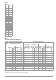


Table Of Contents
- 1 Safety Instructions
- 2 Applications
- 3 Documentation
- 4 Getting Started
- 5 The Instrument
- 6 Operating and Display Elements
- 7 Operation
- 8 Instrument Settings
- 9 Database
- 10 General Information on Measurements
- 10.1 Using Cable Sets and Test Probes
- 10.2 Test Plug – Changing Inserts
- 10.3 Connecting the Instrument
- 10.4 Automatic Settings, Monitoring and Shutdown
- 10.5 Measured Value Display and Memory
- 10.6 Help Function
- 10.7 Setting Parameters or Limit Values using RCD Measurement as an Example
- 10.8 Freely Selectable Parameter Settings or Limit Values
- 10.9 2-Pole Measurement with Rapid or Semiautomatic Polarity Reversal
- 11 Measuring Voltage and Frequency
- 12 Testing RCDs
- 12.1 Measuring Touch Voltage (with reference to nominal residual current) with ⅓ Nominal Residual Current and Tripping Test with Nominal Residual Current
- 12.2 Special Tests for Systems and RCDs
- 12.2.1 Testing Systems and RCCBs with Rising Residual Current (AC) for Type AC, A/F, B/B+ and EV/MI RCDs (PROFITEST MTECH+, PROFITEST MXTRA only)
- 12.2.2 Testing Systems and RCCBs with Rising Residual Current (AC) for Type B/B+ and EV/MI RCDs (PROFITEST MTECH+PROFITEST MXTRA)
- 12.2.3 Testing RCCBS with 5 × IDN
- 12.2.4 Testing of RCCBs which are Suitable for Pulsating DC Residual Current
- 12.3 Testing of Special RCDs
- 12.4 Testing Residual Current Circuit Breakers in TN-S Systems
- 12.5 Testing of RCD Protection in IT Systems with High Cable Capacitance (e.g. In Norway)
- 12.6 Testing of 6 mA Residual Current Devices RDC-DD/RCMB (RDC-DD: PROFITEST MXTRA and PROFITEST MTECH+ only)
- 13 Testing of Breaking Requirements for Overcurrent Protective Devices, Measurement of Loop Impedance and Determination of Short-Circuit Current (ZL-PE and ISC Functions)
- 14 Measuring Supply Impedance (ZL-N Function)
- 15 Earthing Resistance Measurement (Function RE)
- 15.1 Earthing Resistance Measurement – Mains Powered
- 15.2 Earthing Resistance Measurement – Battery Powered, “Battery Mode” (PROFITEST MPRO & PROFITEST MXTRA only)
- 15.3 Earthing Resistance, Mains Powered – 2-Pole Measurement with 2-Pole Adapter or Country-Specific Plug (Schuko) without Probe
- 15.4 Earthing Resistance Measurement. Mains Powered – 3-Pole Measurement: 2-Pole Adapter with Probe
- 15.5 Earthing Resistance Measurement, Mains Powered – Measuring Earth Electrode Potential (UE Function)
- 15.6 Earthing Resistance Measurement, Mains Powered – Selective Earthing Resistance Measurement with Current Clamp Sensor as Accessory
- 15.7 Earthing Resistance Measurement, Battery Powered, “Battery Mode” – 3-Pole (PROFITEST MPRO & PROFITEST MXTRA only)
- 15.8 Earthing Resistance Measurement, Battery Powered, “Battery Mode” – 4-Pole (PROFITEST MPRO & PROFITEST MXTRA only)
- 15.9 Earthing Resistance Measurement, Battery Powered, “Battery Mode” – Selective (4-pole) with Current Clamp Sensor and PRO-RE Measuring Adapter as Accessory (PROFITEST MPRO & PROFITEST MXTRA only)
- 15.10 Earthing Resistance Measurement, Battery Powered, “Battery Mode” – Ground Loop Measurement (with current clamp sensor and transformer, and pro-re measuring adapter as accessory) (PROFITEST MPRO & PROFITEST MXTRA only)
- 15.11 Earthing Resistance Measurement, Battery Powered, “Battery Mode” – Measurement of Soil Resistivity rE (PROFITEST MPRO & PROFITEST MXTRA only)
- 16 Measurement of Insulation Resistance
- 17 Measuring Low-Value Resistance of up to 200 W (Protective Conductor and Equipotential Bonding Conductor)
- 18 Measurement with Accessory Sensors
- 19 Special Functions – EXTRA Switch Position
- 19.1 Voltage Drop Measurement (at ZLN) – DU Function
- 19.2 Measuring the Impedance of Insulating Floors and Walls (standing surface insulation impedance) – ZST Function
- 19.3 Testing Meter Startup with Earthing Contact Plug – kWh Function
- 19.4 Leakage Current Measurement with PRO-AB Leakage Current Adapter as Accessory – IL Function (PROFITEST MXTRA only)
- 19.5 Testing Insulation Monitoring Devices – IMD Function (PROFITEST MXTRA only)
- 19.6 Residual Voltage Test – Ures Function (PROFITEST MXTRA only)
- 19.7 Intelligent Ramp – ta+ID Function (PROFITEST MXTRA only)
- 19.8 Testing Residual Current Monitors – RCM Function ( PROFITEST MXTRA only)
- 19.9 Checking the Operating Statuses of Electric Vehicles at Charging Stations per IEC 61851 ((PROFITEST MTECH+ & PROFITEST MXTRA)
- 19.10 PRCD – Test Sequences for Documenting Fault Simulations at PRCDs with the PROFITEST PRCD Adapter (PROFITEST MXTRA only)
- 20 Test Sequences (Automatic Test Sequences) – AUTO Function
- 21 Maintenance
- 22 Contact, Support and Service
- 23 CE Declaration
- 24 Disposal and Environmental Protection
- 25 Appendix
- 25.1 Tables for Determining Maximum and Minimum Display Values in Consideration of the Instrument’s Maximum Measuring and Intrinsic Uncertainties
- 25.2 At which values should/must an RCD actually be tripped? Requirements for Residual Current Devices (RCD)
- 25.3 Testing Electrical Machines per DIN EN 60 204 – Applications, Limit Values
- 25.4 Periodic Testing per DGUV V 3 (previously BGV A3) – Limit Values for Electrical Systems and Operating Equipment
- 25.5 Bibliography
- 25.6 Internet Addresses for Additional Information

Gossen Metrawatt GmbH 103
Tests for electrical systems include “visual inspection”, “testing”
and “measurement”, and thus may only be conducted by experts
with appropriate work experience.
In the final analysis, the values from VDE 0664 are technically
binding.
25.3 Testing Electrical Machines per DIN EN 60204 –
Applications, Limit Values
The PROFITEST PRIME AC test instrument has been developed
for the testing of electrical machines and controllers. After a revi-
sion to the standard, measurement of loop impedance is now
additionally required. Measurement of loop impedance, as well as
other measurements required for the testing of electrical
machines, can be performed with test instruments from the
PROFITEST MASTER series.
Comparison of Tests Specified by the Standards
Uninterrupted connection of a protective conductor
Uninterrupted connection of a protective conductor system is
tested here by using an alternating current of 0.2 to 10 A with a
line frequency of 50 Hz.
(= low-resistance measurement) Testing must be conducted
between the PE terminal and various points within the protective
conductor system.
Loop Impedance Measurement
Loop impedance Z
L-PE
is measured and short-circuit current I
SC
is ascertained in order to determine if the breaking requirements
for protective devices have been fulfilled (see section 13).
Insulation Resistance Measurement
All of the active conductors in the primary circuit are short-cir-
cuited at the machine (L and N, or L1, L2, L3 and N) and mea-
sured against PE (protective conductor). Controllers or machine
components which are not laid out for these voltages (500 V DC)
can be disconnected from the measuring circuit for the duration
of the measurement. The measured value may not be any less
than 1 M. The test can be subdivided into separate segments.
Voltage Tests (with PROFITEST PRIME AC only)
The electrical equipment of the machine under test must with-
stand a test voltage of twice its own rated voltage value or
1000 V~ (whichever is greater) applied between the conductors of
all circuits and the protective conductor system for a period of at
least 1 second. The test voltage must have a frequency of 50 Hz,
and must be generated by a transformer with a minimum power
rating of 500 VA.
(Residual) Voltage Measurements
The EN 60204 standard specifies that after switching supply
power off, residual voltage must drop to a value of 60 V or less
within 5 seconds at all accessible, active components of a
machine to which a voltage of greater than 60 V is applied during
operation.
When conductors are exposed, residual voltage must drop to a
value of less than or equal to 60 V within 1 second.
Function Test
The machine is operated with nominal voltage and tested for cor-
rect functioning, in particular with regard to safety functions.
Special Tests
• Pulse control mode for troubleshooting
(with PROFITEST PRIME AC only)
• Protective conductor test with 25 A test current
(with PROFITEST PRIME AC only)
Limit Values per DIN EN 60204-1
Overvoltage Protection Device Characteristics for
Limit Value Selection for Protective Conductor Testing
25.4 Periodic Testing per DGUV V 3 (previously BGV A3) – Limit
Values for Electrical Systems and Operating Equipment
Limit Values per EN 50678 / DIN EN 50699
Maximum Permissible Limit Values for Protective Conductor
Resistance for Connector Cables with Lengths of up to 5 m
1
This value may not exceed 1 for permanently connected data pro-
cessing systems (EN 50678 / DIN EN 50699).
2
Total protective conductor resistance: max. 1
Testing per DIN EN 60204-1
(machines)
Testing per DIN EN 61557
(systems)
Measur-
ing
Func-
tion
Uninterrupted connection of a
protective conductor
Part 4: Resistance of:
– Ground conductor
– Protective conductor
– Equipotential bonding conductor
RLO
Loop Impedance Part 3: Loop Impedance ZL-PE
Insulation resistance Part 2: Insulation resistance RISO
Testing for dielectric strength
Part 14: Equipment for testing the
safety of electrical equipment of
machinery
—
Protection against residual
voltage
Part 14: Equipment for testing the
safety of electrical equipment of
machinery
Ures
Function test ——
Measurement Parameters Cross-
Section
Standard
Value
Protective conduc-
tor measurement
Test duration 10 s
Limit value
Protective conductor resis-
tance based on phase
conductor cross-section
and characteristics of the
overvoltage protection de-
vice (calculated value)
1.5 mm²
2.5 mm²
4.0 mm²
6.0 mm²
10 mm²
16 mm²
25 mm² L
(16 mm² PE)
35 mm² L
(16 mm² PE)
50 mm² L
(25 mm² PE)
70 mm² L
(35 mm² PE)
95 mm² L
(50 mm² PE)
120 mm² L
(70 mm² PE)
500 m
500 m
500 m
400 m
300 m
200 m
200 m
100 m
100 m
100 m
050 m
050 m
Insulation resistance
measurement
Nominal voltage 500 V DC
Resistance limit value 1M
Leakage current
measurement
Leakage current 2.0 mA
Protection against
residual voltage
Discharge time after switching off supply
power
5s
Discharge time after exposing conductors 1 s
Testing for dielec-
tric strength
Test voltage 2 × U
N
or 1 kV
Test voltage frequency 50 Hz or 60 Hz
Test duration 1 s
Breaking Time, Characteristics Available for Cross-Section
Fuse breaking time: 5 s All cross-sections
Fuse breaking time: 0.4 s 1.5 through 16 sq. mm
Circuit breaker, characteristic B
Ia = 5 × I
n
- breaking time 0.1 s
1.5 through 16 sq. mm
Circuit breaker, characteristic C
Ia = 10 ×I
n
- breaking time 0.1 s
1.5 through 16 sq. mm
Adjustable circuit breaker
Ia = 8 × I
n
- breaking time: 0.1s
All cross-sections
Test Standard
Test
Current
Open-circuit
voltage
R
SL
Housing – Mains Plug
EN 50678 /
DIN EN 50699
> 200 mA 4 V < U
L
< 24 V
0.3
1
+ 0.1
2
for each additional 7.5 m