
Manual


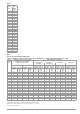


Table Of Contents
- 1 Safety Instructions
- 2 Applications
- 3 Documentation
- 4 Getting Started
- 5 The Instrument
- 6 Operating and Display Elements
- 7 Operation
- 8 Instrument Settings
- 9 Database
- 10 General Information on Measurements
- 10.1 Using Cable Sets and Test Probes
- 10.2 Test Plug – Changing Inserts
- 10.3 Connecting the Instrument
- 10.4 Automatic Settings, Monitoring and Shutdown
- 10.5 Measured Value Display and Memory
- 10.6 Help Function
- 10.7 Setting Parameters or Limit Values using RCD Measurement as an Example
- 10.8 Freely Selectable Parameter Settings or Limit Values
- 10.9 2-Pole Measurement with Rapid or Semiautomatic Polarity Reversal
- 11 Measuring Voltage and Frequency
- 12 Testing RCDs
- 12.1 Measuring Touch Voltage (with reference to nominal residual current) with ⅓ Nominal Residual Current and Tripping Test with Nominal Residual Current
- 12.2 Special Tests for Systems and RCDs
- 12.2.1 Testing Systems and RCCBs with Rising Residual Current (AC) for Type AC, A/F, B/B+ and EV/MI RCDs (PROFITEST MTECH+, PROFITEST MXTRA only)
- 12.2.2 Testing Systems and RCCBs with Rising Residual Current (AC) for Type B/B+ and EV/MI RCDs (PROFITEST MTECH+PROFITEST MXTRA)
- 12.2.3 Testing RCCBS with 5 × IDN
- 12.2.4 Testing of RCCBs which are Suitable for Pulsating DC Residual Current
- 12.3 Testing of Special RCDs
- 12.4 Testing Residual Current Circuit Breakers in TN-S Systems
- 12.5 Testing of RCD Protection in IT Systems with High Cable Capacitance (e.g. In Norway)
- 12.6 Testing of 6 mA Residual Current Devices RDC-DD/RCMB (RDC-DD: PROFITEST MXTRA and PROFITEST MTECH+ only)
- 13 Testing of Breaking Requirements for Overcurrent Protective Devices, Measurement of Loop Impedance and Determination of Short-Circuit Current (ZL-PE and ISC Functions)
- 14 Measuring Supply Impedance (ZL-N Function)
- 15 Earthing Resistance Measurement (Function RE)
- 15.1 Earthing Resistance Measurement – Mains Powered
- 15.2 Earthing Resistance Measurement – Battery Powered, “Battery Mode” (PROFITEST MPRO & PROFITEST MXTRA only)
- 15.3 Earthing Resistance, Mains Powered – 2-Pole Measurement with 2-Pole Adapter or Country-Specific Plug (Schuko) without Probe
- 15.4 Earthing Resistance Measurement. Mains Powered – 3-Pole Measurement: 2-Pole Adapter with Probe
- 15.5 Earthing Resistance Measurement, Mains Powered – Measuring Earth Electrode Potential (UE Function)
- 15.6 Earthing Resistance Measurement, Mains Powered – Selective Earthing Resistance Measurement with Current Clamp Sensor as Accessory
- 15.7 Earthing Resistance Measurement, Battery Powered, “Battery Mode” – 3-Pole (PROFITEST MPRO & PROFITEST MXTRA only)
- 15.8 Earthing Resistance Measurement, Battery Powered, “Battery Mode” – 4-Pole (PROFITEST MPRO & PROFITEST MXTRA only)
- 15.9 Earthing Resistance Measurement, Battery Powered, “Battery Mode” – Selective (4-pole) with Current Clamp Sensor and PRO-RE Measuring Adapter as Accessory (PROFITEST MPRO & PROFITEST MXTRA only)
- 15.10 Earthing Resistance Measurement, Battery Powered, “Battery Mode” – Ground Loop Measurement (with current clamp sensor and transformer, and pro-re measuring adapter as accessory) (PROFITEST MPRO & PROFITEST MXTRA only)
- 15.11 Earthing Resistance Measurement, Battery Powered, “Battery Mode” – Measurement of Soil Resistivity rE (PROFITEST MPRO & PROFITEST MXTRA only)
- 16 Measurement of Insulation Resistance
- 17 Measuring Low-Value Resistance of up to 200 W (Protective Conductor and Equipotential Bonding Conductor)
- 18 Measurement with Accessory Sensors
- 19 Special Functions – EXTRA Switch Position
- 19.1 Voltage Drop Measurement (at ZLN) – DU Function
- 19.2 Measuring the Impedance of Insulating Floors and Walls (standing surface insulation impedance) – ZST Function
- 19.3 Testing Meter Startup with Earthing Contact Plug – kWh Function
- 19.4 Leakage Current Measurement with PRO-AB Leakage Current Adapter as Accessory – IL Function (PROFITEST MXTRA only)
- 19.5 Testing Insulation Monitoring Devices – IMD Function (PROFITEST MXTRA only)
- 19.6 Residual Voltage Test – Ures Function (PROFITEST MXTRA only)
- 19.7 Intelligent Ramp – ta+ID Function (PROFITEST MXTRA only)
- 19.8 Testing Residual Current Monitors – RCM Function ( PROFITEST MXTRA only)
- 19.9 Checking the Operating Statuses of Electric Vehicles at Charging Stations per IEC 61851 ((PROFITEST MTECH+ & PROFITEST MXTRA)
- 19.10 PRCD – Test Sequences for Documenting Fault Simulations at PRCDs with the PROFITEST PRCD Adapter (PROFITEST MXTRA only)
- 20 Test Sequences (Automatic Test Sequences) – AUTO Function
- 21 Maintenance
- 22 Contact, Support and Service
- 23 CE Declaration
- 24 Disposal and Environmental Protection
- 25 Appendix
- 25.1 Tables for Determining Maximum and Minimum Display Values in Consideration of the Instrument’s Maximum Measuring and Intrinsic Uncertainties
- 25.2 At which values should/must an RCD actually be tripped? Requirements for Residual Current Devices (RCD)
- 25.3 Testing Electrical Machines per DIN EN 60 204 – Applications, Limit Values
- 25.4 Periodic Testing per DGUV V 3 (previously BGV A3) – Limit Values for Electrical Systems and Operating Equipment
- 25.5 Bibliography
- 25.6 Internet Addresses for Additional Information

102 Gossen Metrawatt GmbH
25.2 At which values should/must an RCD actually be tripped?
Requirements for Residual Current Devices (RCD)
General Requirements
• Tripping must occur no later than upon occurrence of rated re-
sidual current (nominal differential current I
N
).
and
• Maximum time to trip may not be exceeded.
Additional requirements due to influences on the tripping current range
and the point in time of tripping which have to be taken into consideration:
• Residual current type or waveform:
This results in a reliable tripping current range.
• Mains type and line voltage:
This results in maximum tripping time.
• RCD variant (standard or selective):
This results in maximum tripping time.
Note on RCCBs:
Testing of RCCBs is conducted in accordance with the specifica-
tions set forth in DIN EN 61008-1 (VDE 0664-10) and
DIN EN IEC 61008-2-1 (VDE 0664-1).
Definitions of Requirements in the Standards
VDE 0100-600 (IEC 60364-6), which is included in all German
standards collections for electricians, applies to measurements in
electrical systems. It plainly states: “The effectiveness of the pro-
tective measure is substantiated when disconnection occurs no
later than upon occurrence of rated differential current I
N
.”
As a requirement for the measuring instrument manufacturer,
DIN EN 61557-6 (VDE 0413-6) unmistakably specifies:
“The measuring instrument must be capable of substantiating the
fact that the residual current which trips the residual current
device (RCD) is less than or equal to rated residual current.”
Comment
For all electricians, this means that during required protective
measures testing after system modifications or additions to the
system, as well as after repairs or during the E-check conducted
after measurement of touch voltage, the tripping test must be
conducted no later than upon reaching a value of, depending
upon the RCD, 10, 30, 100, 300 or 500 mA.
How does the electrician react in the event that these values are
exceeded? The RCD is replaced!
If it was relatively new, a complaint is submitted to the manufac-
turer. And in his lab the manufacturer determines: The RCD com-
plies with the manufacturer’s standard and is OK.
A look at the VDE 0664-10/-20/-100/-200 manufacturer’s stan-
dard shows us why:
Because the current waveform plays a significant role, the current
waveform used by the test instrument is also important.
Set residual current type or waveform at the test instrument:
It’s important to be able to select and take advantage of the cor-
responding settings at one’s own test instrument.
The situation is similar for breaking times. The new VDE 0100-410
should also be included in the standards collection.
Depending upon mains type and line voltage, it specifies breaking
times ranging from 0.1 to 5 seconds.
RCDs usually interrupt more quickly, but in some cases they can
take a bit longer. Once again, the ball is in the manufacturer’s
court.
The following table is also included in VDE 0664:
Two limit values are highly conspicuous:
Standard max. 0.3 s
Selective max. 0.5 s
All of the limit values are already included in good test instru-
ments, or it’s possible to enter them directly and they’re displayed
as well!
Select or set limit values at the test instrument:
Type of Residual Current Residual Current
Waveform
Permissible
Tripping Current
Range
Sinusoidal alternating current 0.5 … 1 I
N
Pulsating direct current
(positive or negative half-waves)
0.35 … 1.4 I
N
Phase angle controlled
half-wave currents
Phase angle of 90° el
Phase angle of 135° el
0.25 … 1.4 I
N
0.11 … 1.4 I
N
Pulsating direct current
superimposed with 6 mA smooth,
direct residual current
Max. 1.4 I
N
+ 6 mA
Smooth direct current 0.5 … 2 I
N
System
50 V < U
0
120 V
120 V < U0 £
230 V
230 V < U0 £
400 V
U
0
> 400 V
AC DC AC DC AC DC AC DC
TN
0.8 s 0.4 s 5 s 0.2 s 0.4 s 0.1 s 0.1 s
TT
0.3 s 0.2 s 0.4 s 0.07 s 0.2 s 0.04 s 0.1 s
Design
Residual
Current
Type
Breaking Time at
Alternating
residual
current
1 ×
I
N
2 × I
N
5 × I
N
500 A
Pulsating
direct residual
current
1.4 ×
I
N
2 × 1.4 × I
N
5 × 1.4 × I
N
500 A
Smooth, direct
residual
current
2 ×
I
N
2 × 2 × I
N
5 × 2 × I
N
500 A
Standard
(undelayed) or
briefly delayed
300ms Max. 0.15 s Max. 0.04 s Max. 0.04 s
Selective 0.13 … 0.5 s 0.06 … 0.2 s 0.05 … 0.15 s 0.04 … 0.15 s
Negative half-wave
Positive half-wave
Waveform:
Negative direct current
Positive direct current