
User Manual
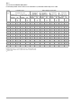
Table Of Contents
- 1 Scope of Delivery
- 2 Application
- 3 Safety Features and Precautions
- 4 Initial Start-Up
- 5 General Notes
- 5.1 Connecting the Instrument
- 5.2 Automatic Settings, Monitoring and Shut-Off
- 5.3 Measurement Value Display and Memory
- 5.4 Testing Earthing Contact Sockets for Correct Connection
- 5.5 Help Function
- 5.6 Setting Parameters or Limit Values using RCD Measurement as an Example
- 5.7 Freely Selectable Parameter Settings or Limit Values
- 5.8 2-Pole Measurement with Fast or Semiautomatic Polarity Reversal
- 6 Measuring Voltage and Frequency
- 7 Testing RCDs
- 8 Testing of Breaking Requirements for Overcurrent Protective Devices, Measurement of Loop Impedance and Determination of Short-Circuit Current (functions ZL-PE and IK)
- 9 Measuring Line Impedance (ZL-N function)
- 10 Earthing Resistance Measurement (RE function)
- 11 Measurement of Insulation Resistance
- 12 Measuring Low-Value Resistance up to 200 Ohm (protective conductor and equipotential bonding conductor)
- 13 Special Functions – EXTRA Switch Position
- 14 Database
- 15 Attaching the Test Probe Holder to the Carrying Strap
- 16 LED Indications, Mains Connections and Potential Differences
- 17 Characteristic Values
- 18 Maintenance
- 19 Appendix
- 19.1 Tables for Determining Maximum or Minimum Display Values in Consideration of Maximum Measuring Uncertainty
- 19.2 At which values should/must an RCD actually be tripped? Requirements for Residual Current Devices (RCDs)
- 19.3 Periodic Testing per DGUV Regulations 3 (formerly BGV A3) – Limit Values for Electrical Systems and Operating Equipment
- 19.4 Optional Accessories (not included)
- 19.5 List of Abbreviations and their Meanings
- 19.6 Keyword Index
- 19.7 Bibliography
- 20 Repair and Replacement Parts Service Calibration Center* and Rental Instrument Service
- 21 Recalibration
- 22 Product Support

GMC-I Messtechnik GmbH 59
19.6 Keyword Index
A
Abbreviations ..........................................................................58
Adjusting Brightness and Contrast ..........................................11
B
Batteries
Charge Level .....................................................................4
Installation .........................................................................8
Bibliography ............................................................................60
D
Data Backup .............................................................................7
DB MODE ...............................................................................11
Default Settings (GOME SETTING) ..........................................11
E
Earth Leakage Resistance .......................................................34
F
Firmware Revision and Calibration Information ........................12
Firmware Update ....................................................................12
Fuse
Checking .........................................................................53
FUSE Message ................................................................53
Replacement ...................................................................53
I
Internet Addresses ..................................................................60
L
Limit Values
DINVDE0701-0702 ..........................................................57
Line Voltage (display of UL-N) .................................................28
Line-to-Line Voltage ................................................................17
M
MASTER Updater ...................................................................12
Memory
Occupancy Display
............................................................4
N
No-Trip Test ............................................................................21
O
On-Time
LCD Illumination
...............................................................11
Test Instrument ................................................................11
P
Parameter Lock ......................................................................14
Phase Sequence .....................................................................17
Plausibility Check ....................................................................14
Polarity Reversal .....................................................................15
Power Management ..........................................................13, 51
PRCD
Tripping Test, Type PRCD-K ............................................22
Tripping Test, Type PRCD-S ............................................23
Profiles for Distributor Structures (PROFILES) ..........................11
R
RCD-S ....................................................................................22
Return and Environmentally Sound Disposal
...........................53
S
Safety Shutdown ....................................................... 13, 44, 51
SCHUKOMAT .........................................................................23
Short-Circuit Current Calculation
.............................................27
SIDOS ....................................................................................23
SRCD .....................................................................................23
Standard
DIN EN 50178 (VDE 160) .................................................21
DIN VDE 0100 ...........................................................25, 30
DIN VDE 0100-410
..........................................................22
DIN VDE 0100-600 ............................................... 6, 20, 26
EN 1081 ..........................................................................34
NIV/NIN SEV 1000
.............................................................6
ÖVE/ÖNORM E 8601 ......................................................24
ÖVE-EN 1 ......................................................................... 6
VDE 0413 ....................................................................... 25
Symbols ................................................................................... 7
T
Testing
DGUV Regulation 3 ......................................................... 57
Touch Voltage ........................................................................ 19
Type G RCCBs ....................................................................... 24
U
User Interface Language (CULTURE) ...................................... 11
V
Voltage Drop as % (ZL-N function) ......................................... 37
Voltage Drop Measurement .................................................... 37