
User Manual
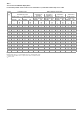
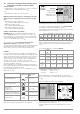
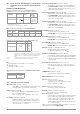
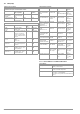
Table Of Contents
- 1 Scope of Delivery
- 2 Application
- 3 Safety Features and Precautions
- 4 Initial Start-Up
- 5 General Notes
- 5.1 Connecting the Instrument
- 5.2 Automatic Settings, Monitoring and Shut-Off
- 5.3 Measurement Value Display and Memory
- 5.4 Testing Earthing Contact Sockets for Correct Connection
- 5.5 Help Function
- 5.6 Setting Parameters or Limit Values using RCD Measurement as an Example
- 5.7 Freely Selectable Parameter Settings or Limit Values
- 5.8 2-Pole Measurement with Fast or Semiautomatic Polarity Reversal
- 6 Measuring Voltage and Frequency
- 7 Testing RCDs
- 8 Testing of Breaking Requirements for Overcurrent Protective Devices, Measurement of Loop Impedance and Determination of Short-Circuit Current (functions ZL-PE and IK)
- 9 Measuring Line Impedance (ZL-N function)
- 10 Earthing Resistance Measurement (RE function)
- 11 Measurement of Insulation Resistance
- 12 Measuring Low-Value Resistance up to 200 Ohm (protective conductor and equipotential bonding conductor)
- 13 Special Functions – EXTRA Switch Position
- 14 Database
- 15 Attaching the Test Probe Holder to the Carrying Strap
- 16 LED Indications, Mains Connections and Potential Differences
- 17 Characteristic Values
- 18 Maintenance
- 19 Appendix
- 19.1 Tables for Determining Maximum or Minimum Display Values in Consideration of Maximum Measuring Uncertainty
- 19.2 At which values should/must an RCD actually be tripped? Requirements for Residual Current Devices (RCDs)
- 19.3 Periodic Testing per DGUV Regulations 3 (formerly BGV A3) – Limit Values for Electrical Systems and Operating Equipment
- 19.4 Optional Accessories (not included)
- 19.5 List of Abbreviations and their Meanings
- 19.6 Keyword Index
- 19.7 Bibliography
- 20 Repair and Replacement Parts Service Calibration Center* and Rental Instrument Service
- 21 Recalibration
- 22 Product Support

58 GMC-I Messtechnik GmbH
19.5 List of Abbreviations and their Meanings
RCCB (residual current circuit breaker)
I
∆
Tripping current
I
∆N
Nominal residual current
I
F
Rising test current (residual current)
PRCD Portable residual current device
PRCD-S:
with protective conductor detection and monitoring
PRCD-K:
with undervoltage trigger and protective conductor monitor-
ing
RCD- Selective RCCB
R
E
Calculated earthing or earth electrode loop resistance
SRCD Socket residual current device (permanently installed)
t
a
Time to trip / breaking time
U
I∆
Touch voltage at moment of tripping
U
I∆N
Touch voltage relative to nominal residual current I
∆N
U
L
Touch voltage limit value
Overcurrent Protective Devices
I
K
Calculated short-circuit current (at nominal voltage)
Z
L-N
Line impedance
Z
L-PE
Loop impedance
Earthing
R
B
Operational earth resistance
R
E
Measured earthing resistance
R
ELoop
Earth electrode loop resistance
Low-Value Resistance at
Protective, Earthing and Bonding Conductors
R
LO+
Bonding conductor resistance (+ pole to PE)
R
LO–
Bonding conductor resistance (– pole to PE)
Insulation
R
E(INS)
Earth leakage resistance (DIN 51953)
R
INS
Insulation resistance
Current
I
A
Breaking current
I
M
Measuring current
I
N
Nominal current
I
P
Test current
Voltage
f Line voltage frequency
f
N
Nominal voltage rated frequency
∆U Voltage drop as %
U Voltage measured at the test probes during and after insu-
lation measurement R
INS
U
Batt
(Rechargeable) battery voltage
U
E
Earth electrode voltage
U
INS
For measurement of R
INS
: test voltage, for ramp function:
triggering or breakdown voltage
U
L-L
Voltage between two phase conductors
U
L-N
Voltage between L and N
U
L-PE
Voltage between L and PE
U
N
Nominal line voltage
U
3~
Highest measured voltage during determination of phase
sequence
U
Y
Phase voltage to earth
S