
User Manual
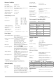
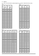
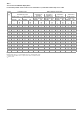
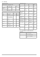
Table Of Contents
- 1 Scope of Delivery
- 2 Application
- 3 Safety Features and Precautions
- 4 Initial Start-Up
- 5 General Notes
- 5.1 Connecting the Instrument
- 5.2 Automatic Settings, Monitoring and Shut-Off
- 5.3 Measurement Value Display and Memory
- 5.4 Testing Earthing Contact Sockets for Correct Connection
- 5.5 Help Function
- 5.6 Setting Parameters or Limit Values using RCD Measurement as an Example
- 5.7 Freely Selectable Parameter Settings or Limit Values
- 5.8 2-Pole Measurement with Fast or Semiautomatic Polarity Reversal
- 6 Measuring Voltage and Frequency
- 7 Testing RCDs
- 8 Testing of Breaking Requirements for Overcurrent Protective Devices, Measurement of Loop Impedance and Determination of Short-Circuit Current (functions ZL-PE and IK)
- 9 Measuring Line Impedance (ZL-N function)
- 10 Earthing Resistance Measurement (RE function)
- 11 Measurement of Insulation Resistance
- 12 Measuring Low-Value Resistance up to 200 Ohm (protective conductor and equipotential bonding conductor)
- 13 Special Functions – EXTRA Switch Position
- 14 Database
- 15 Attaching the Test Probe Holder to the Carrying Strap
- 16 LED Indications, Mains Connections and Potential Differences
- 17 Characteristic Values
- 18 Maintenance
- 19 Appendix
- 19.1 Tables for Determining Maximum or Minimum Display Values in Consideration of Maximum Measuring Uncertainty
- 19.2 At which values should/must an RCD actually be tripped? Requirements for Residual Current Devices (RCDs)
- 19.3 Periodic Testing per DGUV Regulations 3 (formerly BGV A3) – Limit Values for Electrical Systems and Operating Equipment
- 19.4 Optional Accessories (not included)
- 19.5 List of Abbreviations and their Meanings
- 19.6 Keyword Index
- 19.7 Bibliography
- 20 Repair and Replacement Parts Service Calibration Center* and Rental Instrument Service
- 21 Recalibration
- 22 Product Support

GMC-I Messtechnik GmbH 55
Table 5
Short-Circuit Current Minimum Display Values
for determining nominal current for various fuses and breakers for systems with nominal voltage of U
N
= 230 V
Example
Display value 90.4 A → next smaller value for circuit breaker char-
acteristic B from table: 85 A → protective device nominal current
(I
N
) max. 16 A
Nominal
Current
I
N
[A]
Low Resistance Fuses
per the DIN VDE 0636 series of standards
With Circuit Breaker and Line Switch
Characteristic gL, gG, gM Characteristic B/E
(formerly L)
Characteristic C
(formerly G, U)
Characteristic D
Characteristic K
Breaking Current I
A
5 s Breaking Current I
A
0.4 s Breaking Current I
A
5 x I
N
(< 0.2 s/0.4 s)
Breaking Current I
A
10 x I
N
(< 0.2 s/0.4 s)
Breaking Current I
A
20 x I
N
(< 0.2 s/0.4 s)
Breaking Current I
A
12 x I
N
(< 0.1 s)
Limit Value
[A]
Min.
Display
[A]
Limit Value
[A]
Min.
Display
[A]
Limit Value
[A]
Min.
Display
[A]
Limit Value
[A]
Min.
Display
[A]
Limit Value
[A]
Min.
Display
[A]
Limit Value
[A]
Min.
Display
[A]
2 9.2 10 16 17 10 11 20 21 40 42 24 25
314.11524251516303260643638
4192032342021404280854851
627284750303260641201287276
8373965694042808516017296102
10 47 50 82 87 50 53 100 106 200 216 120 128
13 56 59 98 104 65 69 130 139 260 297 156 167
16 65 69 107 114 80 85 160 172 320 369 192 207
20 85 90 145 155 100 106 200 216 400 467 240 273
25 110 117 180 194 125 134 250 285 500 578 300 345
32 150 161 265 303 160 172 320 369 640 750 384 447
35 173 186 295 339 175 188 350 405 700 825 420 492
40 190 205 310 357 200 216 400 467 800 953 480 553
50 260 297 460 529 250 285 500 578 1000 1.22 k 600 700
63 320 369 550 639 315 363 630 737 1260 1.58 k 756 896
80 440 517 960 1.16 k
100 580 675 1200 1.49 k
125 750 889 1440 1.84 k
160 930 1.12 k 1920 2.59 k