
User Manual
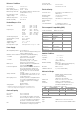
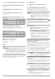
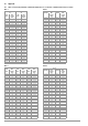
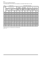
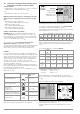
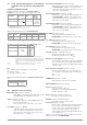
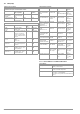
Table Of Contents
- 1 Scope of Delivery
- 2 Application
- 3 Safety Features and Precautions
- 4 Initial Start-Up
- 5 General Notes
- 5.1 Connecting the Instrument
- 5.2 Automatic Settings, Monitoring and Shut-Off
- 5.3 Measurement Value Display and Memory
- 5.4 Testing Earthing Contact Sockets for Correct Connection
- 5.5 Help Function
- 5.6 Setting Parameters or Limit Values using RCD Measurement as an Example
- 5.7 Freely Selectable Parameter Settings or Limit Values
- 5.8 2-Pole Measurement with Fast or Semiautomatic Polarity Reversal
- 6 Measuring Voltage and Frequency
- 7 Testing RCDs
- 8 Testing of Breaking Requirements for Overcurrent Protective Devices, Measurement of Loop Impedance and Determination of Short-Circuit Current (functions ZL-PE and IK)
- 9 Measuring Line Impedance (ZL-N function)
- 10 Earthing Resistance Measurement (RE function)
- 11 Measurement of Insulation Resistance
- 12 Measuring Low-Value Resistance up to 200 Ohm (protective conductor and equipotential bonding conductor)
- 13 Special Functions – EXTRA Switch Position
- 14 Database
- 15 Attaching the Test Probe Holder to the Carrying Strap
- 16 LED Indications, Mains Connections and Potential Differences
- 17 Characteristic Values
- 18 Maintenance
- 19 Appendix
- 19.1 Tables for Determining Maximum or Minimum Display Values in Consideration of Maximum Measuring Uncertainty
- 19.2 At which values should/must an RCD actually be tripped? Requirements for Residual Current Devices (RCDs)
- 19.3 Periodic Testing per DGUV Regulations 3 (formerly BGV A3) – Limit Values for Electrical Systems and Operating Equipment
- 19.4 Optional Accessories (not included)
- 19.5 List of Abbreviations and their Meanings
- 19.6 Keyword Index
- 19.7 Bibliography
- 20 Repair and Replacement Parts Service Calibration Center* and Rental Instrument Service
- 21 Recalibration
- 22 Product Support

GMC-I Messtechnik GmbH 51
Reference Conditions
Line voltage 230 V ± 0.1%
Line frequency 50 Hz ± 0.1%
Meas. quantity frequency
45 Hz … 65 Hz
Measured qty. waveform
Sine (deviation between effective and
rectified value ≤ 0.1%)
Line impedance angle cos ϕ =1
Supply voltage 12 V ± 0.5 V
Ambient temperature +22 °C ±3 K
Relative humidity 45% ±10%
Nominal Ranges of Use
Voltage U
N
120 V (108 ... 132 V)
230 V (196 ... 253 V)
400 V (340 ... 440 V)
Frequency f
N
16⅔ Hz (15.4 ... 18 Hz)
50 Hz (49.5 ... 50.5 Hz)
60 Hz (59.4 ... 60.6 Hz)
200 Hz (190 ... 210 Hz)
400 Hz (380 ... 420 Hz)
Overall voltage range U
Y
65 ... 550 V
Overall frequency range 15.4 ... 420 Hz
Waveform Sinusoidal
Temperature range 0 °C ... + 40 °C
Supply voltage 8 ... 12 V
Line impedance angle Corresponds to cos ϕ = 1 ... 0.95
Power Supply
(Rechargeable) batteries 8 each AA 1.5 V
We recommend using the battery pack
(article number: Z502H).
Number of measurements (standard setup with illumination)
– For R
INS
1 measurement – 25 s pause:
approx. 600 measurements
– For R
LO
Auto polarity reversal / 1 Ω
(1 measuring cycle) – 25 s pause:
approx. 800 measurements
Battery test Symbolic display of rechargeable bat-
tery voltage
Power management
Display illumination can be switched off.
The test instrument is switched off
automatically after the last key opera-
tion. The user can select the desired
on-time.
Safety shutdown If supply voltage is too low (U < 8.0 V),
the instrument is switched off, or can-
not be switched on.
Recharging socket Installed, optional rechargeable batter-
ies can be recharged directly by con-
necting a charger to the recharging
socket:
Z502R charger
Charging time Approx. 2 hours *
* Maximum charging time with fully depleted rechargeable batteries.
A timer in the charger limits charging time to no more than 4 hours.
Overload Capacity
U
L-PE
, U
L-N
600 V continuous
RCD, R
E
440 V continuous
Z
L-PE
, Z
L-N
550 V (Limits the number of measure-
ments and pause duration. If overload
occurs, the instrument is switched off
by means of a thermostatic switch.)
R
LO
Electronic protection prevents switching
on if interference voltage is present.
Protection with
two fine-wire fuse FF 3.15 A 10 s,
Fuses blow at > 5 A
Electrical Safety
Protection class II per IEC 61010-1/EN 61010-1/
VDE 0411-1
Nominal voltage 230/400 V (300/500 V)
Test voltage 3.7 kV 50 Hz
Measuring category CAT III 600 V or CAT IV 300 V
Pollution degree 2
Fuses
L and N terminals 1 cartridge fuse-link ea.
FF 3.15 A/600 V 6.3 x 32 mm
Electromagnetic Compatibility (EMC)
Product Standard EN 61326-1:2006
Ambient Conditions
Accuracy 0 to + 40° C
Operation -5 ... + 50°C
Storage -20 ... + 60°C
(without batteries)
Relative humidity
Max. 75%
(max. 85% during storage/transport)
no condensation allowed
Elevation Max. 2000 m
Calibration interval 1 year (recommended)
Mechanical Design
Display Multiple display with dot matrix,
128 x 128 pixels,
backlit (transflective),
dimensions: 65 x 65 mm
Dimensions W x L x D: 225 x 130 x 140 mm
Weight Approx. 1.5 kg with batteries
Protection Housing: IP 52, connections: IP 40
per EN 60529/DIN VDE 0470-1
Excerpt from Table on the Meaning of IP Codes
Data Interfaces
Type USB slave for connection to a PC
Type RS-232 for barcode and RFID readers
BAT
Interference emission Class
EN 55022 A
Interference immunity Te st Value Feature
EN 61000-4-2 Contact/atmos. –
4 kV/8 kV
EN 61000-4-3 10 V/m
EN 61000-4-4 Mains connection –
2 kV
EN 61000-4-5 Mains connection –
1 kV
EN 61000-4-6 Mains connection –
3 V
EN 61000-4-11 0.5 periods / 100%
IP XY
(1
st
digit X)
Protection Against
Foreign Object Ingress
IP XY
(2
nd
digit Y)
Protection Against Pene-
tration by Water
4 ≥ 1.0 mm dia. 0 Not protected
5 Dust protected 2 Dripping (at 15° angle)