
User Manual
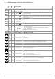
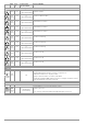
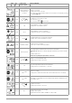
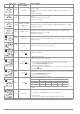
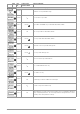
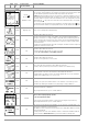

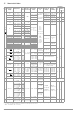
Table Of Contents
- 1 Scope of Delivery
- 2 Application
- 3 Safety Features and Precautions
- 4 Initial Start-Up
- 5 General Notes
- 5.1 Connecting the Instrument
- 5.2 Automatic Settings, Monitoring and Shut-Off
- 5.3 Measurement Value Display and Memory
- 5.4 Testing Earthing Contact Sockets for Correct Connection
- 5.5 Help Function
- 5.6 Setting Parameters or Limit Values using RCD Measurement as an Example
- 5.7 Freely Selectable Parameter Settings or Limit Values
- 5.8 2-Pole Measurement with Fast or Semiautomatic Polarity Reversal
- 6 Measuring Voltage and Frequency
- 7 Testing RCDs
- 8 Testing of Breaking Requirements for Overcurrent Protective Devices, Measurement of Loop Impedance and Determination of Short-Circuit Current (functions ZL-PE and IK)
- 9 Measuring Line Impedance (ZL-N function)
- 10 Earthing Resistance Measurement (RE function)
- 11 Measurement of Insulation Resistance
- 12 Measuring Low-Value Resistance up to 200 Ohm (protective conductor and equipotential bonding conductor)
- 13 Special Functions – EXTRA Switch Position
- 14 Database
- 15 Attaching the Test Probe Holder to the Carrying Strap
- 16 LED Indications, Mains Connections and Potential Differences
- 17 Characteristic Values
- 18 Maintenance
- 19 Appendix
- 19.1 Tables for Determining Maximum or Minimum Display Values in Consideration of Maximum Measuring Uncertainty
- 19.2 At which values should/must an RCD actually be tripped? Requirements for Residual Current Devices (RCDs)
- 19.3 Periodic Testing per DGUV Regulations 3 (formerly BGV A3) – Limit Values for Electrical Systems and Operating Equipment
- 19.4 Optional Accessories (not included)
- 19.5 List of Abbreviations and their Meanings
- 19.6 Keyword Index
- 19.7 Bibliography
- 20 Repair and Replacement Parts Service Calibration Center* and Rental Instrument Service
- 21 Recalibration
- 22 Product Support

46 GMC-I Messtechnik GmbH
Err14
SETUP
Resistance compensation for the connector cables:
R
OFFSET
> 1 Ω:
OFFSET measurement of RL-PE or RN-PE and RLN for ZL-PE and ZL-N is not
sensible.
Remedy: check system.
Err15 R
LO
R
OFFSET
> 10 Ω:
OFFSET measurement is not sensible.
Remedy: check system.
Err16
SETUP → OFFSET
(EXTRA → ∆U)
Z > 10 Ω:
OFFSET measurement of RL-PE or RN-PE and RLN for ∆U(ZLN) is not sensible.
Remedy: check system.
Err17 EXTRA → ∆U
∆U
OFFSET
> ∆U:
OFFSET value is greater than the measured value at the consuming system.
OFFSET measurement is not sensible.
Remedy: check system.
Err18
RINS
/ RLO
Contact problem or blown fuse
Remedy: check test plug or measuring adapter for correct seating in the test plug,
or replace the fuse.
Err19
R
E
Polarity of the test probes has to be reversed.
Err20 I
∆N
/ I
F
N and PE are swapped.
Err21
I
∆N
/ I
F
Z
L-N
/ Z
L-PE
/ R
E
1) Mains connection error
Remedy: inspect mains connection.
or
2) Display in the connection pictograph: PE interrupted (x) or bottom protective
conductor tab interrupted with reference to the keys at the test plug
Cause: voltage measuring path interrupted
Result: measurement is disabled.
Note: only if appears: Measurement can nevertheless be started by pressing
the
ON/START key again.
Err22
I
∆N
/ I
F
Display in the connection pictograph:
Top protective conductor tab interrupted with reference to the keys at the test plug
Cause: current measuring path interrupted
Result: no measured value display
Err23 I
∆N
/ I
F
Resistance in the N-PE path is too high.
Consequence: The required test current cannot be generated and measurement is
aborted.
Err24 Z
L-PE
, R
E
If specified touch voltage U
L
is exceeded:
Z
L-PE
and R
E
: user is prompted to switch to the 15 mA wave.
R
E
alternative only:
User is prompted to reduce the measuring range (reduce current.)
Status
Error
No.
Position of the
Function Switch
Function / Meaning
I
∆N
/I
F
10 mA 30 mA 100 mA 300 mA 500 mA
R
MAX
at I
∆N
510 Ω 170 Ω 50 Ω 15 Ω 9 Ω
R
MAX
for I
F
410 Ω 140 Ω 40 Ω 12 Ω 7 Ω