
User Manual
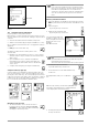
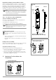
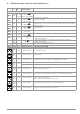
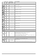
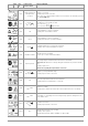
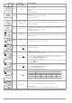
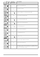
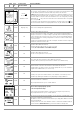

Table Of Contents
- 1 Scope of Delivery
- 2 Application
- 3 Safety Features and Precautions
- 4 Initial Start-Up
- 5 General Notes
- 5.1 Connecting the Instrument
- 5.2 Automatic Settings, Monitoring and Shut-Off
- 5.3 Measurement Value Display and Memory
- 5.4 Testing Earthing Contact Sockets for Correct Connection
- 5.5 Help Function
- 5.6 Setting Parameters or Limit Values using RCD Measurement as an Example
- 5.7 Freely Selectable Parameter Settings or Limit Values
- 5.8 2-Pole Measurement with Fast or Semiautomatic Polarity Reversal
- 6 Measuring Voltage and Frequency
- 7 Testing RCDs
- 8 Testing of Breaking Requirements for Overcurrent Protective Devices, Measurement of Loop Impedance and Determination of Short-Circuit Current (functions ZL-PE and IK)
- 9 Measuring Line Impedance (ZL-N function)
- 10 Earthing Resistance Measurement (RE function)
- 11 Measurement of Insulation Resistance
- 12 Measuring Low-Value Resistance up to 200 Ohm (protective conductor and equipotential bonding conductor)
- 13 Special Functions – EXTRA Switch Position
- 14 Database
- 15 Attaching the Test Probe Holder to the Carrying Strap
- 16 LED Indications, Mains Connections and Potential Differences
- 17 Characteristic Values
- 18 Maintenance
- 19 Appendix
- 19.1 Tables for Determining Maximum or Minimum Display Values in Consideration of Maximum Measuring Uncertainty
- 19.2 At which values should/must an RCD actually be tripped? Requirements for Residual Current Devices (RCDs)
- 19.3 Periodic Testing per DGUV Regulations 3 (formerly BGV A3) – Limit Values for Electrical Systems and Operating Equipment
- 19.4 Optional Accessories (not included)
- 19.5 List of Abbreviations and their Meanings
- 19.6 Keyword Index
- 19.7 Bibliography
- 20 Repair and Replacement Parts Service Calibration Center* and Rental Instrument Service
- 21 Recalibration
- 22 Product Support

42 GMC-I Messtechnik GmbH
Data Evaluation and Report Generation with ETC Software
All data, including the distributor structure, can be transferred to
the PC and evaluated with the help of ETC software. Additional
information can be entered here subsequently for the individual
measurements. After pressing the appropriate key, a report
including all measurements within a given distributor structure is
generated, or the data are exported to an Excel spreadsheet.
Note
The database is exited when the rotary selector switch is
turned. Previously selected parameters in the database
are not used for the measurement.
14.4.1 Use of Barcode Scanners and RFID Readers
Search for an Already Scanned Barcode
The search can be started from any switch setting and menu.
➭ Scan the object’s barcode.
The found barcode is displayed inversely.
➭ This value is accepted after pressing the ENTER key.
Note
A previously selected object is not taken into consider-
ation by the search.
Continued Searching in General
Regardless of whether or not an object has been found,
searching can be continued by pressing the key shown at
the left:
– Object found: Searching is continued underneath the previ-
ously selected object.
– No further object found: The entire database is searched at
all levels.
Reading In a Barcode for Editing
If the menu for alphanumeric entry is active, any value scanned by
means of a barcode or RFID reader is accepted directly.
Using a Barcode Printer (accessory)
A barcode printer allows for the following applications:
• Read-out of ID numbers as barcodes, encrypted; for quick
and convenient acquisition for periodic testing
• Print-out of repeatedly occurring designations such as test
object types encrypted as barcodes in a list, allowing them to
be read in as required for comments
15 Attaching the Test Probe Holder to the
Carrying Strap
1
Bottom Right
Detach the strap from the
instrument: Turn out the slotted screw
(M3) at the bottom.
Bottom Left
Carrying
Clasp
Clasp
Front View
2
Slide the strap through the test probe
holder.
Side View
Eyelet for Tester (PROFITEST INTRO,
METRISO INTRO, BASE, TECH, PRO, XTRA)
Strap
3
Front
Feed the strap through from the front
of the test instrument and secure it
with the slotted screw (M3).
Back