
User Manual
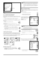
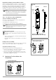
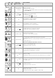
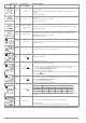
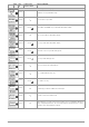
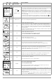

Table Of Contents
- 1 Scope of Delivery
- 2 Application
- 3 Safety Features and Precautions
- 4 Initial Start-Up
- 5 General Notes
- 5.1 Connecting the Instrument
- 5.2 Automatic Settings, Monitoring and Shut-Off
- 5.3 Measurement Value Display and Memory
- 5.4 Testing Earthing Contact Sockets for Correct Connection
- 5.5 Help Function
- 5.6 Setting Parameters or Limit Values using RCD Measurement as an Example
- 5.7 Freely Selectable Parameter Settings or Limit Values
- 5.8 2-Pole Measurement with Fast or Semiautomatic Polarity Reversal
- 6 Measuring Voltage and Frequency
- 7 Testing RCDs
- 8 Testing of Breaking Requirements for Overcurrent Protective Devices, Measurement of Loop Impedance and Determination of Short-Circuit Current (functions ZL-PE and IK)
- 9 Measuring Line Impedance (ZL-N function)
- 10 Earthing Resistance Measurement (RE function)
- 11 Measurement of Insulation Resistance
- 12 Measuring Low-Value Resistance up to 200 Ohm (protective conductor and equipotential bonding conductor)
- 13 Special Functions – EXTRA Switch Position
- 14 Database
- 15 Attaching the Test Probe Holder to the Carrying Strap
- 16 LED Indications, Mains Connections and Potential Differences
- 17 Characteristic Values
- 18 Maintenance
- 19 Appendix
- 19.1 Tables for Determining Maximum or Minimum Display Values in Consideration of Maximum Measuring Uncertainty
- 19.2 At which values should/must an RCD actually be tripped? Requirements for Residual Current Devices (RCDs)
- 19.3 Periodic Testing per DGUV Regulations 3 (formerly BGV A3) – Limit Values for Electrical Systems and Operating Equipment
- 19.4 Optional Accessories (not included)
- 19.5 List of Abbreviations and their Meanings
- 19.6 Keyword Index
- 19.7 Bibliography
- 20 Repair and Replacement Parts Service Calibration Center* and Rental Instrument Service
- 21 Recalibration
- 22 Product Support

GMC-I Messtechnik GmbH 41
If no further matches are found, the message shown above is dis-
played.
14.4 Saving Data and Generating Reports
Preparing and Executing a Measurement
Measurements can be performed and stored to memory for each
structure element. Proceed as follows, adhering to the prescribed
sequence:
➭ Select the desired measurement with the rotary knob.
➭ Start the measurement by pressing the
ON/START or I∆
N
key.
Upon completion of measurement, the “→ Floppy Disk” softkey is
displayed.
➭ Briefly press the “Save Value” key.
The display is switched to the memory menu or the
structure view.
➭ Navigate to the desired memory location, i.e. to the desired
structure element / object, for which the measurement data
will be saved.
➭ If you would like to save a comment along with the
measurement, press the key shown at the right and
enter a designation via the “EDIT” menu as described in
section 14.3.1.
➭ Complete data storage by pressing the “STORE” key.
Saving Error Messages (pop-ups)
If a measurement is ended without a measured value due to an
error, the measurement can be saved along with the pop-up by
pressing the “Save Value” key. The corresponding text is read out
in ETC instead of the pop-up symbol. This only applies to a limited
number of pop-ups (see below). Neither a symbol nor a text can
be accessed in the test instrument’s database itself.
Alternative Storage Procedure
➭ The measured value can be saved to the last se-
lected object in the structure diagram by pressing
and holding the “Save Value” key, without switching
the display to the memory menu.
Note
If you change the parameters in the measurement view,
they are not saved for the structure element. A measure-
ment with changed parameters can nevertheless be
saved to the structure element, and any changed param-
eters are documented in the report for each measure-
ment.
Retrieving Saved Measured Values
➭ Switch the display to the distributor structure by pressing the
MEM key and select the desired electrical circuit with the scroll
keys.
➭ Switch to page 2
by pressing the key shown here:
➭ Display the measurement data
by pressing the key shown here:
One measurement with date
and time, as well as any com-
ment you might have entered, is
displayed in each screen.
Example:
RCD Measurement
Note
A check mark in the header means that the respective
measurement has been passed.
An X means that the measurement has not been passed.
➭ Scrolling amongst measurements
is possible with the keys shown here:
➭ The measurement can be deleted with the key
shown here:
A prompt window asks you to confirm dele-
tion.
With the help of the key shown at the right (MW: mea-
sured value / PA: parameter), the setting parameters
can be displayed for this measurement.
➭ Scrolling amongst measurements is possible with
the keys shown here:
End search