
User Manual
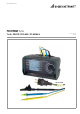
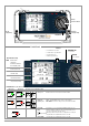
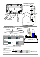
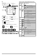
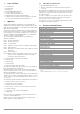
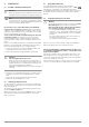
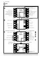
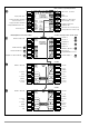
Table Of Contents
- 1 Scope of Delivery
- 2 Application
- 3 Safety Features and Precautions
- 4 Initial Start-Up
- 5 General Notes
- 5.1 Connecting the Instrument
- 5.2 Automatic Settings, Monitoring and Shut-Off
- 5.3 Measurement Value Display and Memory
- 5.4 Testing Earthing Contact Sockets for Correct Connection
- 5.5 Help Function
- 5.6 Setting Parameters or Limit Values using RCD Measurement as an Example
- 5.7 Freely Selectable Parameter Settings or Limit Values
- 5.8 2-Pole Measurement with Fast or Semiautomatic Polarity Reversal
- 6 Measuring Voltage and Frequency
- 7 Testing RCDs
- 8 Testing of Breaking Requirements for Overcurrent Protective Devices, Measurement of Loop Impedance and Determination of Short-Circuit Current (functions ZL-PE and IK)
- 9 Measuring Line Impedance (ZL-N function)
- 10 Earthing Resistance Measurement (RE function)
- 11 Measurement of Insulation Resistance
- 12 Measuring Low-Value Resistance up to 200 Ohm (protective conductor and equipotential bonding conductor)
- 13 Special Functions – EXTRA Switch Position
- 14 Database
- 15 Attaching the Test Probe Holder to the Carrying Strap
- 16 LED Indications, Mains Connections and Potential Differences
- 17 Characteristic Values
- 18 Maintenance
- 19 Appendix
- 19.1 Tables for Determining Maximum or Minimum Display Values in Consideration of Maximum Measuring Uncertainty
- 19.2 At which values should/must an RCD actually be tripped? Requirements for Residual Current Devices (RCDs)
- 19.3 Periodic Testing per DGUV Regulations 3 (formerly BGV A3) – Limit Values for Electrical Systems and Operating Equipment
- 19.4 Optional Accessories (not included)
- 19.5 List of Abbreviations and their Meanings
- 19.6 Keyword Index
- 19.7 Bibliography
- 20 Repair and Replacement Parts Service Calibration Center* and Rental Instrument Service
- 21 Recalibration
- 22 Product Support

4 GMC-I Messtechnik GmbH
Key
Overview of Device Settings and Measuring Functions
Battery display
Measuring function
Measurement in
Memory occupancy
Measured
Parameter
Display Panel
PE
Save value
Battery full
Battery OK
Battery weak
Battery (almost) dead
Battery Display
BAT
BAT
BAT
BAT
Memory Occupancy Display
MEM
Memory half full
MEM
Memory full > transfer data to PC
Connection Test – Mains Connection Test (→ section 16)
N
PE
L
N
PE
L
)(
Connection OK L and N reversed
N
PE
L N
PE
L
x
N
PE
L N
PE
L
x
x
RUN READY
Connection test → section 16
U < 8 V
L
PE
N
These operating instructions describe a tester
with software version SW-VERSION (SW1) 01.20.00.
progress / stopped
quantities
Switch
Setting
descrip-
tion as of
Picto-
graph
Device settings
Measuring Functions
SETUP
page 9
Brightness, contrast, time/date
Language (D, GB, P), profiles (ETC, PS3, PC.doc)
Default settings
< Test: LED, LCD, acoustic signal
Battery test
Measurements with Line Voltage
U
page 16
Single-phase measurement, U
L-N-PE
UL-N Voltage between L and N
UL-PE Voltage between L and PE
UN-PE Voltage between N and PE
f Frequency
3-phase measurement U
3~
UL3-L1 Voltage between L3 and L1
UL1-L2 Voltage between L1 and L2
UL2-L3 Voltage between L2 and L3
f Frequency
Phase sequence
Appears for all
measurements shown
below:
U / U
N
Line voltage / nominal line voltage
f / f
N
Line frequency / nominal line frequency
I∆N
page 18
UI∆N Touch voltage
ta Tripping time
RE Earth resistance
IF
page 20
UI∆N Touch voltage
I∆ Residual current
RE Earth resistance
ZL-PE
page 25
ZL-PE Loop impedance
IK Short-circuit current
ZL-N
page 27
ZL-N Line impedance
IK Short-circuit current
RE
page 29
2-pole meas. (ground loop) RE(L-PE)
2-pole meas. / country-specific plug
Measurements at voltage-free objects
RLO
page 35
RLO Low-resistance with polarity reversal
RLO+, RLO–
Low-resistance, single-pole
ROFFSET Offset resistance
RINS
page 32
RINS Insulation resistance
RE(INS) Earth leakage resistance
U Voltage at the test probes
UINS Test voltage
Ramp: triggering/breakdown voltage
EXTRA
page 37
∆U Voltage drop measurement