
User Manual
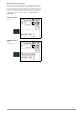
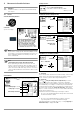
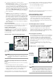
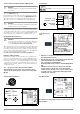
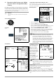
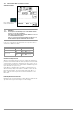
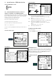
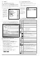
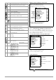
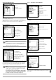
Table Of Contents
- 1 Scope of Delivery
- 2 Application
- 3 Safety Features and Precautions
- 4 Initial Start-Up
- 5 General Notes
- 5.1 Connecting the Instrument
- 5.2 Automatic Settings, Monitoring and Shut-Off
- 5.3 Measurement Value Display and Memory
- 5.4 Testing Earthing Contact Sockets for Correct Connection
- 5.5 Help Function
- 5.6 Setting Parameters or Limit Values using RCD Measurement as an Example
- 5.7 Freely Selectable Parameter Settings or Limit Values
- 5.8 2-Pole Measurement with Fast or Semiautomatic Polarity Reversal
- 6 Measuring Voltage and Frequency
- 7 Testing RCDs
- 8 Testing of Breaking Requirements for Overcurrent Protective Devices, Measurement of Loop Impedance and Determination of Short-Circuit Current (functions ZL-PE and IK)
- 9 Measuring Line Impedance (ZL-N function)
- 10 Earthing Resistance Measurement (RE function)
- 11 Measurement of Insulation Resistance
- 12 Measuring Low-Value Resistance up to 200 Ohm (protective conductor and equipotential bonding conductor)
- 13 Special Functions – EXTRA Switch Position
- 14 Database
- 15 Attaching the Test Probe Holder to the Carrying Strap
- 16 LED Indications, Mains Connections and Potential Differences
- 17 Characteristic Values
- 18 Maintenance
- 19 Appendix
- 19.1 Tables for Determining Maximum or Minimum Display Values in Consideration of Maximum Measuring Uncertainty
- 19.2 At which values should/must an RCD actually be tripped? Requirements for Residual Current Devices (RCDs)
- 19.3 Periodic Testing per DGUV Regulations 3 (formerly BGV A3) – Limit Values for Electrical Systems and Operating Equipment
- 19.4 Optional Accessories (not included)
- 19.5 List of Abbreviations and their Meanings
- 19.6 Keyword Index
- 19.7 Bibliography
- 20 Repair and Replacement Parts Service Calibration Center* and Rental Instrument Service
- 21 Recalibration
- 22 Product Support

GMC-I Messtechnik GmbH 39
Distributor Structure Symbology / Tree Structure
14.3.1 Creating Structures (example for electrical circuit)
After selection with the MEM key, all setting options for the cre-
ation of a tree structure are made available on three menu pages
(1/3, 2/3 and 3/3). The tree structure consists of structure ele-
ments, referred to below as objects.
Select the position at which a new object will be added.
Use the ↑↓ keys in order to select structure elements.
Change to the sub-level with the ↵ key.
Go to the next page with the >> key
Creating a New Object
Press the key in order to create a new object.
Show measurement data, if a measurement has
been performed for this structure element.
Edit the selected structure element.
Memory menu, page 3 of 3
Search for ID number
> Enter complete ID number.
Search for text.
> Enter full text (complete word).
Search for ID number or text.
Continue searching.
Edit menu
Cursor LEFT:
Select an alphanumeric character
Cursor RIGHT:
Select an alphanumeric character
ENTER: accept an individual character
←
→
Acknowledge entry
Scroll left
Scroll right
Delete characters.
Switching amongst different types of alphanu-
meric characters:
A Upper case letters
a Lower case letters
0Numbers
@ Special characters
Symbol Meaning
Distributor
A check mark to the right of a structure element means that all measurements
within the respective hierarchy have been passed.
x: At least one measurement has not been passed.
No symbol: Measurement has not yet been performed.
Building
Customer
RCD
Circuit
Equipment
Same type of element as in the Windows Explorer:
+: sub-objects available, display by pressing ↵.
–: sub-objects are displayed, hide by pressing ↵.
Equipment
Scroll up
Scroll down
Acknowledge selection /
Display object
Next page
change level
or ID number
Create object
Delete object
VΩA: show measurement data
Edit designation