
User Manual
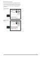
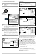
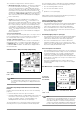
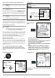
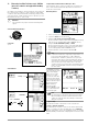
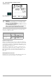
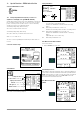
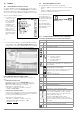
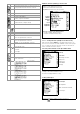
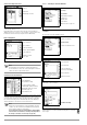
Table Of Contents
- 1 Scope of Delivery
- 2 Application
- 3 Safety Features and Precautions
- 4 Initial Start-Up
- 5 General Notes
- 5.1 Connecting the Instrument
- 5.2 Automatic Settings, Monitoring and Shut-Off
- 5.3 Measurement Value Display and Memory
- 5.4 Testing Earthing Contact Sockets for Correct Connection
- 5.5 Help Function
- 5.6 Setting Parameters or Limit Values using RCD Measurement as an Example
- 5.7 Freely Selectable Parameter Settings or Limit Values
- 5.8 2-Pole Measurement with Fast or Semiautomatic Polarity Reversal
- 6 Measuring Voltage and Frequency
- 7 Testing RCDs
- 8 Testing of Breaking Requirements for Overcurrent Protective Devices, Measurement of Loop Impedance and Determination of Short-Circuit Current (functions ZL-PE and IK)
- 9 Measuring Line Impedance (ZL-N function)
- 10 Earthing Resistance Measurement (RE function)
- 11 Measurement of Insulation Resistance
- 12 Measuring Low-Value Resistance up to 200 Ohm (protective conductor and equipotential bonding conductor)
- 13 Special Functions – EXTRA Switch Position
- 14 Database
- 15 Attaching the Test Probe Holder to the Carrying Strap
- 16 LED Indications, Mains Connections and Potential Differences
- 17 Characteristic Values
- 18 Maintenance
- 19 Appendix
- 19.1 Tables for Determining Maximum or Minimum Display Values in Consideration of Maximum Measuring Uncertainty
- 19.2 At which values should/must an RCD actually be tripped? Requirements for Residual Current Devices (RCDs)
- 19.3 Periodic Testing per DGUV Regulations 3 (formerly BGV A3) – Limit Values for Electrical Systems and Operating Equipment
- 19.4 Optional Accessories (not included)
- 19.5 List of Abbreviations and their Meanings
- 19.6 Keyword Index
- 19.7 Bibliography
- 20 Repair and Replacement Parts Service Calibration Center* and Rental Instrument Service
- 21 Recalibration
- 22 Product Support

38 GMC-I Messtechnik GmbH
14 Database
14.1 Creating Distributor Structures, General
A complete distributor structure with data for electrical circuits
and RCDs can be created in the PROFITEST INTRO test instrument.
This structure makes it possible to assign measurements to the
electrical circuits of various distributors, buildings and customers.
There are two possible procedures:
• On location or at the
construction site:
create the distribu-
tor structure in the
test instrument.
A distributor struc-
ture with up to
50,000 structure ele-
ments can be cre-
ated in the test
instrument, which is
saved to the instru-
ment’s flash mem-
ory.
or
• Create and save an image of an existing distributor structure
at a PC with the help of ETC report generating software (Electric
Testing Center) – see Help > Getting Started (F1). The distrib-
utor structure is then transferred to the test instrument.
Note regarding ETC Report Generating Software
The following steps must be completed before using the soft-
ware:
• Installing the USB Device Driver
(required for operation of the PROFITEST INTRO at a PC):
GMC-I Driver Control software for installing the USB device
driver can be downloaded from our website:
http://www.gossenmetrawatt.com
→ Products → Software → Software for Testers
→ Utilities → Driver Control
• Install ETC report generating software:
The most up-to-date version of ETC can be downloaded free
of charge from the mygmc page of our website as a ZIP file, if
you have registered your test instrument:
http://www.gossenmetrawatt.com
→ Products → Software → Software for Testers
→ Report Software without Database → ETC
→ myGMC
→ to Login
14.2 Transferring Distributor Structures
The following data transfer operations are possible:
• Transfer a distributor structure from the PC to the test instru-
ment.
• Transfer a distributor structure including measured values
from the test instrument to the PC.
The test instrument and
the PC must be con-
nected with a USB cable
in order to transfer struc-
tures and data.
The following image
appears at the display
during transfer of struc-
tures and data.
14.3 Creating a Distributor Structure in the Test Instrument
Overview of the Meanings of Icons used to Create Structures
Symbol Meaning
Main
Level
Sub-
Level
Memory menu, page 1 of 3
Cursor UP: scroll up
Cursor DOWN: scroll down
ENTER: acknowledge selection
+ → – change to sub-level
(open directory) or
– → + change to main level
(close directory)
Display the complete structure designation (max.
63 characters) or ID number (25 characters) in a
zoom window
Temporarily switch back and forth between struc-
ture designation and ID number.
These keys don’t have any effect on the main set-
ting in the setup menu (see “DB Mode” on
page 11).
Hide the zoom window
Change display to menu selection
Memory menu, page 2 of 3
Add a structure element
Meanings of icons from top to bottom:
Customer, building, distributor, RCD, electrical cir-
cuit, operating equipment, machine and earth
electrode (display of the icons depends on the
selected structure element).
Selection: UP/DOWN scroll keys and ↵
In order to add a designation to the selected
structure element, refer to the edit menu in follow-
ing column.
EDIT
For additional icons see edit menu below
Delete the selected structure element.