
User Manual
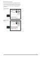
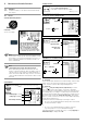
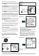
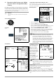
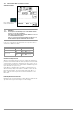
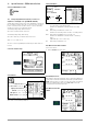
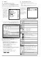
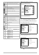
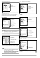
Table Of Contents
- 1 Scope of Delivery
- 2 Application
- 3 Safety Features and Precautions
- 4 Initial Start-Up
- 5 General Notes
- 5.1 Connecting the Instrument
- 5.2 Automatic Settings, Monitoring and Shut-Off
- 5.3 Measurement Value Display and Memory
- 5.4 Testing Earthing Contact Sockets for Correct Connection
- 5.5 Help Function
- 5.6 Setting Parameters or Limit Values using RCD Measurement as an Example
- 5.7 Freely Selectable Parameter Settings or Limit Values
- 5.8 2-Pole Measurement with Fast or Semiautomatic Polarity Reversal
- 6 Measuring Voltage and Frequency
- 7 Testing RCDs
- 8 Testing of Breaking Requirements for Overcurrent Protective Devices, Measurement of Loop Impedance and Determination of Short-Circuit Current (functions ZL-PE and IK)
- 9 Measuring Line Impedance (ZL-N function)
- 10 Earthing Resistance Measurement (RE function)
- 11 Measurement of Insulation Resistance
- 12 Measuring Low-Value Resistance up to 200 Ohm (protective conductor and equipotential bonding conductor)
- 13 Special Functions – EXTRA Switch Position
- 14 Database
- 15 Attaching the Test Probe Holder to the Carrying Strap
- 16 LED Indications, Mains Connections and Potential Differences
- 17 Characteristic Values
- 18 Maintenance
- 19 Appendix
- 19.1 Tables for Determining Maximum or Minimum Display Values in Consideration of Maximum Measuring Uncertainty
- 19.2 At which values should/must an RCD actually be tripped? Requirements for Residual Current Devices (RCDs)
- 19.3 Periodic Testing per DGUV Regulations 3 (formerly BGV A3) – Limit Values for Electrical Systems and Operating Equipment
- 19.4 Optional Accessories (not included)
- 19.5 List of Abbreviations and their Meanings
- 19.6 Keyword Index
- 19.7 Bibliography
- 20 Repair and Replacement Parts Service Calibration Center* and Rental Instrument Service
- 21 Recalibration
- 22 Product Support

GMC-I Messtechnik GmbH 37
13 Special Functions – EXTRA Switch Position
Select the EXTRA Switch Position
13.1 Voltage Drop Measurement (at Z
LN
) – Function ∆U
Significance and Display of ∆U (per DIN VDE 100-600)
Voltage drop from the intersection of the distribution network and
the consumer system to the point of connection of an electrical
power consumer
(electrical outlet or device connector terminals)
should not exceed 5% of nominal line voltage.
Calculating voltage drop (without offset):
∆U = Z
L-N
• nominal current of the fuse
Calculating voltage drop (with offset):
∆U = (Z
L-N
- Z
OFFSET
) • nominal current of the fuse
∆U in % = 100 • ∆U / U
L-N
See also section 9 regarding measurement procedure and con-
nection.
Connection and Test Setup
Set Parameters
Note: If nominal current I
N
is changed by prevailing ∆U
OFFSET
, the
offset value is automatically adapted.
Setting Limit Values
TAB Limit value per German technical connection conditions
for connection to low-voltage mains
between the distribution network and the measuring
device
DIN Limit value per DIN 18015-1: ∆U < 3%
between the measuring device and the consuming device
VDE Limit value per DIN VDE 0100-520: ∆U <
5%
between the distribution network and the consuming
device
(adjustable up to 10% in this case)
NL Limit value per NIV: ∆U < 5%
Start Measurement without OFFSET
Proceed as follows:
➭ Switch OFFSET from ON to OFF.
Determining RLN OFFSET
Depending on which measurement cable or measuring adapter is
connected, an offset measurement must first be performed in the
SETUP switch position (see page 12). The offset value ascertained
in this way is displayed in the footer as RLN OFFSET and is sub-
tracted from the measurement results.
Start Measurement with
OFFSET
EXTRA
1
2
Nom. fuse current: 2 to 160 A
Polarity selection: Lx-N
Diameter: 1.5 to 70 sq. mm
Cable types:
NY..., H03... - H07...
Number of wires: 2 to 10 strand
Tripping characteristics: B, L
Limit Value:
∆U % > Limit Value
U
L
R
L
∆U
Red
2