
User Manual
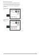
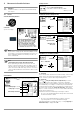
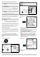
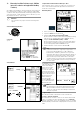
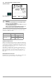
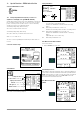
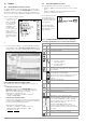
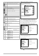
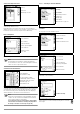
Table Of Contents
- 1 Scope of Delivery
- 2 Application
- 3 Safety Features and Precautions
- 4 Initial Start-Up
- 5 General Notes
- 5.1 Connecting the Instrument
- 5.2 Automatic Settings, Monitoring and Shut-Off
- 5.3 Measurement Value Display and Memory
- 5.4 Testing Earthing Contact Sockets for Correct Connection
- 5.5 Help Function
- 5.6 Setting Parameters or Limit Values using RCD Measurement as an Example
- 5.7 Freely Selectable Parameter Settings or Limit Values
- 5.8 2-Pole Measurement with Fast or Semiautomatic Polarity Reversal
- 6 Measuring Voltage and Frequency
- 7 Testing RCDs
- 8 Testing of Breaking Requirements for Overcurrent Protective Devices, Measurement of Loop Impedance and Determination of Short-Circuit Current (functions ZL-PE and IK)
- 9 Measuring Line Impedance (ZL-N function)
- 10 Earthing Resistance Measurement (RE function)
- 11 Measurement of Insulation Resistance
- 12 Measuring Low-Value Resistance up to 200 Ohm (protective conductor and equipotential bonding conductor)
- 13 Special Functions – EXTRA Switch Position
- 14 Database
- 15 Attaching the Test Probe Holder to the Carrying Strap
- 16 LED Indications, Mains Connections and Potential Differences
- 17 Characteristic Values
- 18 Maintenance
- 19 Appendix
- 19.1 Tables for Determining Maximum or Minimum Display Values in Consideration of Maximum Measuring Uncertainty
- 19.2 At which values should/must an RCD actually be tripped? Requirements for Residual Current Devices (RCDs)
- 19.3 Periodic Testing per DGUV Regulations 3 (formerly BGV A3) – Limit Values for Electrical Systems and Operating Equipment
- 19.4 Optional Accessories (not included)
- 19.5 List of Abbreviations and their Meanings
- 19.6 Keyword Index
- 19.7 Bibliography
- 20 Repair and Replacement Parts Service Calibration Center* and Rental Instrument Service
- 21 Recalibration
- 22 Product Support

34 GMC-I Messtechnik GmbH
Special Condition for Insulation Resistance Measurement
Attention!
!
Insulation resistance can only be measured at voltage-
free objects.
If measured insulation resistance is less than the selected limit
value, the LIMIT LED lights up.
If an interference voltage of
≥ 25 V is present within the system,
insulation resistance is not measured. The MAINS/NETZ LED lights
up and the “interference voltage” pop-up message appears.
All conductors (L1, L2, L3 and N) must be tested against PE!
Attention!
!
Do not touch the instrument’s terminal contacts during
insulation resistance measurements!
If nothing has been connected to the terminal contacts, or if a
resistive load component has been connected for measurement,
your body would be exposed to a current of approximately 1 mA
at a voltage of 1000 V. However, the resultant perceptible shock
may lead to injury (e.g. resulting from a startled reaction etc.).
Discharging the Device Under Test
Attention!
!
If measurement is performed at a capacitive object such
as a long cable, it becomes charged with up to approx.
1000 V! Touching such objects is life endangering!
When an insulation resistance measurement has been performed
on a capacitive object it’s automatically discharged by the instru-
ment after measurement has been completed. Contact with the
device under test must be maintained to this end. The falling volt-
age value can be observed at the U display.
Do not disconnect the DUT until less than 10 V is displayed for U!
Evaluation of Measured Values
Instrument measuring error must be taken into consideration in
order to assure that the limit values set forth in DIN VDE regula-
tions are not fallen short of. The required minimum display values
for insulation resistance can be determined with the help of Table
3 on page 54. These values take maximum device error into con-
sideration (under nominal conditions of use). Intermediate values
can be interpolated.
11.2 Special Case: Earth Leakage Resistance (REINS)
This measurement is performed in order to determine electro-
static discharge capacity for floor coverings in accordance with
EN 1081.
Select the Measuring Function
Set Parameters
* Freely adjustable voltage (see section 5.7)
Connection and Test
Setup
➭ Rub the floor covering at the point at which measurement is to
be performed with a dry cloth.
➭ Place the 1081 floor probe onto the point of measurement and
load it with a weight of at least 300 N (30 kg).
This corresponds to standard EN 1081.
A load with 750 N (75 kg) conforms to standard DIN VDE 0100-
600.
➭ Establish a conductive connection between the measuring
electrode and the test probe and connect the measuring
adapter (2-pole) to an earth contact, e.g. the earthing contact
at a mains outlet or a central heating radiator (prerequisite:
reliable ground connection).
Start Measurement
The limit value for earth leakage resistance from the relevant reg-
ulations applies.
R
INS
Limit Value:
RE(INS) > limit value
LIMIT
R
EINS
Voltage type: constant
Test voltage
:
50 V / 100 V / 250 V / 325 V / 500 V / 1000 V*
Voltage type: rising/ramp
Earth leakage
resistance: