
User Manual
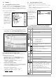
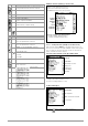
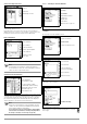
Table Of Contents
- 1 Scope of Delivery
- 2 Application
- 3 Safety Features and Precautions
- 4 Initial Start-Up
- 5 General Notes
- 5.1 Connecting the Instrument
- 5.2 Automatic Settings, Monitoring and Shut-Off
- 5.3 Measurement Value Display and Memory
- 5.4 Testing Earthing Contact Sockets for Correct Connection
- 5.5 Help Function
- 5.6 Setting Parameters or Limit Values using RCD Measurement as an Example
- 5.7 Freely Selectable Parameter Settings or Limit Values
- 5.8 2-Pole Measurement with Fast or Semiautomatic Polarity Reversal
- 6 Measuring Voltage and Frequency
- 7 Testing RCDs
- 8 Testing of Breaking Requirements for Overcurrent Protective Devices, Measurement of Loop Impedance and Determination of Short-Circuit Current (functions ZL-PE and IK)
- 9 Measuring Line Impedance (ZL-N function)
- 10 Earthing Resistance Measurement (RE function)
- 11 Measurement of Insulation Resistance
- 12 Measuring Low-Value Resistance up to 200 Ohm (protective conductor and equipotential bonding conductor)
- 13 Special Functions – EXTRA Switch Position
- 14 Database
- 15 Attaching the Test Probe Holder to the Carrying Strap
- 16 LED Indications, Mains Connections and Potential Differences
- 17 Characteristic Values
- 18 Maintenance
- 19 Appendix
- 19.1 Tables for Determining Maximum or Minimum Display Values in Consideration of Maximum Measuring Uncertainty
- 19.2 At which values should/must an RCD actually be tripped? Requirements for Residual Current Devices (RCDs)
- 19.3 Periodic Testing per DGUV Regulations 3 (formerly BGV A3) – Limit Values for Electrical Systems and Operating Equipment
- 19.4 Optional Accessories (not included)
- 19.5 List of Abbreviations and their Meanings
- 19.6 Keyword Index
- 19.7 Bibliography
- 20 Repair and Replacement Parts Service Calibration Center* and Rental Instrument Service
- 21 Recalibration
- 22 Product Support

GMC-I Messtechnik GmbH 33
The constant test voltage function offers two options:
• After briefly pressing the
ON/START key, specified test voltage U
N
is read out and insulation resistance R
INS
is measured. As
soon as the measured value is stable (settling time may be
several seconds in the case of high cable capacitance values),
measurement is ended and the last measured values for R
INS
and U
INS
are displayed. U is the voltage which is measured at
the test probes during and after testing. This voltage drops to a
value of less than 10 V (see section entitled “Discharging the
Device Under Test”).
or
• As long as you press the
ON/START key, test voltage U
N
is
applied and insulation resistance R
INS
is measured. Do not
release the key until the measured value has settled in (settling
time may be several seconds in the case of high cable capac-
itance values). Voltage U, which is measured during testing,
corresponds to voltage U
INS
. After releasing the
ON/START key,
measurement is ended and the last measured values for R
INS
and U
INS
are displayed. U drops to a value of less than 10 V
after measurement (see the section entitled “Discharging the
Device Under Test”.
❏ Pole Selection Report Entry
The poles between which testing takes place can only be entered
here for reporting purposes. The entry itself has no influence on
the actual polarity of the test probes or the pole selection.
❏ Limits – Setting the Limit Value
The limit value for insulation resistance can be set as desired. If
measurement values occur which are below this limit value, the
red LIMIT LED lights up. A selection of limit values ranging from
0.5 MΩ to 10 MΩ is available. The limit value is displayed above
the measured value.
Start Measurement – Rising Test Voltage (ramp function)
Press briefly:
Quick polarity reversal if parameter is set to AUTO: 01/10 ... 10/10:
L1-PE ... L1-L3
Note
If “semiautomatic polarity reversal” is selected (see sec-
tion 5.8), the corresponding icon is displayed instead of
the ramp.
General Notes Regarding Insulation Measurements with Ramp
Function
Insulation measurement with ramp function serves the following
purposes:
• Detect weak points in the test object’s insulation.
• Determine tripping voltage of voltage limiting components and
test them for correct functioning. These components may
include, for example, varistors, overvoltage limiters (e.g.
DEHNguard® from Dehn+Söhne) and spark gaps.
The test instrument uses continuously rising test voltage for this
measuring function, up to the maximum selected voltage limit.
The measuring procedure is started by pressing the
ON/START key
and runs automatically until one of the following events occurs:
• The selected voltage limit is reached
• The selected current limit is reached
or
• Sparkover occurs (spark gaps)
Differentiation is made amongst the following three procedures for
insulation measurement with ramp function:
Testing overvoltage limiters or varistors
and determining their tripping voltage:
– Select maximum voltage such that the anticipated breakdown
voltage of the device under test is roughly one third of this
value (observe manufacturer’s data sheet if applicable).
– Select current limit value in accordance with actual require-
ments or the manufacturer’s data sheet (characteristic curve
of the device under test).
Determining tripping voltage for spark gaps:
– Select maximum voltage such that the anticipated breakdown
voltage of the device under test is roughly one third of this
value (observe manufacturer’s data sheet if applicable).
– Select the current limit value in accordance with actual
requirements within a range of 5 to 10 μA (response charac-
teristics are too unstable with larger current limit values, which
may result in faulty measurement results).
Detect weak points in the insulation:
– Select maximum voltage such that it does not exceed the test
object’s permissible insulation voltage; it can be assumed that
an insulation fault will occur even with a significantly lower
voltage if an accordingly lower maximum voltage value is
selected (nevertheless at least greater than anticipated break-
down voltage) – the ramp is less steep as a result (increased
measuring accuracy).
– Select the current limit value in accordance with actual
requirements within a range of 5 to 10 μA (see also settings
for spark gaps).
Start Measurement – Constant Test Voltage
For long-term
measurements
Press and hold:
Quick polarity reversal if parameter is set to AUTO: 01/10 ... 10/10:
L1-PE ... L1-L3
Note
The instrument’s (rechargeable) batteries are exposed to
excessive stress during insulation resistance measure-
ment. When using the “constant test voltage” function,
only press and hold the
ON/START key until the display has
become stable (if long-term measurement is required).