
User Manual
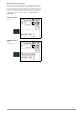
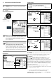
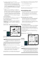
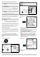
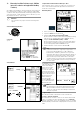
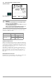
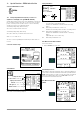
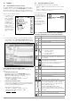
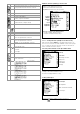
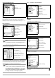
Table Of Contents
- 1 Scope of Delivery
- 2 Application
- 3 Safety Features and Precautions
- 4 Initial Start-Up
- 5 General Notes
- 5.1 Connecting the Instrument
- 5.2 Automatic Settings, Monitoring and Shut-Off
- 5.3 Measurement Value Display and Memory
- 5.4 Testing Earthing Contact Sockets for Correct Connection
- 5.5 Help Function
- 5.6 Setting Parameters or Limit Values using RCD Measurement as an Example
- 5.7 Freely Selectable Parameter Settings or Limit Values
- 5.8 2-Pole Measurement with Fast or Semiautomatic Polarity Reversal
- 6 Measuring Voltage and Frequency
- 7 Testing RCDs
- 8 Testing of Breaking Requirements for Overcurrent Protective Devices, Measurement of Loop Impedance and Determination of Short-Circuit Current (functions ZL-PE and IK)
- 9 Measuring Line Impedance (ZL-N function)
- 10 Earthing Resistance Measurement (RE function)
- 11 Measurement of Insulation Resistance
- 12 Measuring Low-Value Resistance up to 200 Ohm (protective conductor and equipotential bonding conductor)
- 13 Special Functions – EXTRA Switch Position
- 14 Database
- 15 Attaching the Test Probe Holder to the Carrying Strap
- 16 LED Indications, Mains Connections and Potential Differences
- 17 Characteristic Values
- 18 Maintenance
- 19 Appendix
- 19.1 Tables for Determining Maximum or Minimum Display Values in Consideration of Maximum Measuring Uncertainty
- 19.2 At which values should/must an RCD actually be tripped? Requirements for Residual Current Devices (RCDs)
- 19.3 Periodic Testing per DGUV Regulations 3 (formerly BGV A3) – Limit Values for Electrical Systems and Operating Equipment
- 19.4 Optional Accessories (not included)
- 19.5 List of Abbreviations and their Meanings
- 19.6 Keyword Index
- 19.7 Bibliography
- 20 Repair and Replacement Parts Service Calibration Center* and Rental Instrument Service
- 21 Recalibration
- 22 Product Support

32 GMC-I Messtechnik GmbH
11 Measurement of Insulation Resistance
Attention!
!
Insulation resistance can only be measured at voltage-
free objects.
11.1 General
Select the Measuring Function
Connection
2-pole or test plug
Note
If you use the country-specific measuring adapter, insula-
tion resistance is only measured between the phase con-
ductor terminal designated “L” and the protective con-
ductor terminal PE!
Note
Checking Measurement Cables Before Measurements
Before performing insulation measurement, the test
probes on the measurement cables should be short-cir-
cuited in order to assure that the instrument displays a
value of less than 1 kΩ. In this way, incorrect connection
can be avoided and broken measurement cables can be
detected.
Set Parameters
* Freely adjustable voltage (see section 5.7)
Polarity Selection
* AUTO parameter (see section 5.8)
Breakdown Current for Ramp Function
Limit Values for Breakdown Voltage
Limit Values for Constant Test Voltage
❏ Test voltage
A test voltage which deviates from nominal voltage, and is usually
lower, can be selected for measurements at sensitive compo-
nents, as well as systems with voltage limiting devices.
❏ Voltage type
The “U
INS
” rising test voltage function (ramp function) is used to
detect weak points in the insulation, as well as to determine
response voltage for voltage limiting components. After pressing
the
ON/START key, test voltage is continuously increased until the
specified nominal voltage U
N
is reached. U is the voltage which is
measured at the test probes during and after testing. This voltage
drops to a value of less than 10 V (see section entitled “Discharg-
ing the Device Under Test”).
Insulation measurement with rising test voltage is ended:
• As soon as specified maximum test voltage U
N
is reached and
the measured value is stable
or
• As soon as specified maximum test voltage is reached
(e.g. after sparkover occurs at breakdown voltage).
Specified maximum test voltage U
N
or any occurring triggering or
breakdown voltage is displayed for U
INS
.
R
INS
Voltage type: constant
Test voltage
:
50 V / 100 V / 250 V / 325 V / 500 V / 1000 V
Voltage type: rising/ramp
Earth leakage resistance:
xxx V*
2-pole measurement (selection relevant for report genera-
ting only), measurements between:
Lx-PE / N-PE / L+N-PE / Lx-N / Lx-Ly / AUTO*
where x, y = 1, 2, 3
Limit Value:
I > I
Limit
U
INS
(U
INS
)
STOP
Lower limit value:
U
INS
(U
INS
)
Enterable range:
40 to 999 V
Upper limit value:
Limit Value:
R
INS
< Limit Value
LIMIT
U
INS
(U
INS
)