
User Manual
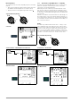
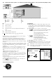
Table Of Contents
- 1 Scope of Delivery
- 2 Application
- 3 Safety Features and Precautions
- 4 Initial Start-Up
- 5 General Notes
- 5.1 Connecting the Instrument
- 5.2 Automatic Settings, Monitoring and Shut-Off
- 5.3 Measurement Value Display and Memory
- 5.4 Testing Earthing Contact Sockets for Correct Connection
- 5.5 Help Function
- 5.6 Setting Parameters or Limit Values using RCD Measurement as an Example
- 5.7 Freely Selectable Parameter Settings or Limit Values
- 5.8 2-Pole Measurement with Fast or Semiautomatic Polarity Reversal
- 6 Measuring Voltage and Frequency
- 7 Testing RCDs
- 8 Testing of Breaking Requirements for Overcurrent Protective Devices, Measurement of Loop Impedance and Determination of Short-Circuit Current (functions ZL-PE and IK)
- 9 Measuring Line Impedance (ZL-N function)
- 10 Earthing Resistance Measurement (RE function)
- 11 Measurement of Insulation Resistance
- 12 Measuring Low-Value Resistance up to 200 Ohm (protective conductor and equipotential bonding conductor)
- 13 Special Functions – EXTRA Switch Position
- 14 Database
- 15 Attaching the Test Probe Holder to the Carrying Strap
- 16 LED Indications, Mains Connections and Potential Differences
- 17 Characteristic Values
- 18 Maintenance
- 19 Appendix
- 19.1 Tables for Determining Maximum or Minimum Display Values in Consideration of Maximum Measuring Uncertainty
- 19.2 At which values should/must an RCD actually be tripped? Requirements for Residual Current Devices (RCDs)
- 19.3 Periodic Testing per DGUV Regulations 3 (formerly BGV A3) – Limit Values for Electrical Systems and Operating Equipment
- 19.4 Optional Accessories (not included)
- 19.5 List of Abbreviations and their Meanings
- 19.6 Keyword Index
- 19.7 Bibliography
- 20 Repair and Replacement Parts Service Calibration Center* and Rental Instrument Service
- 21 Recalibration
- 22 Product Support

30 GMC-I Messtechnik GmbH
10.1 Earth Resistance, Mains Operation – 2-Pole Measurement with KS-PROFITEST INTRO or Country-Specific Measuring Adapter (Schuko)
Key
R
B
Operational earth
R
E
Earth resistance
R
i
Internal resistance
R
X
Earthing resistance through equipotential bonding sys-
tems
R
S
Probe resistance
PAS Equipotential bonding busbar
RE Overall earthing resistance (R
E1
//R
E2
//water pipe)
Earthing resistance can be estimated without a probe using the
“earth loop resistance measurement”.
The resistance value R
ELoop
obtained with this measuring
method also includes operational earth electrode resistance R
B
and resistance at phase conductor L. These values must be
deducted from the measured value in order to determine earthing
resistance.
If conductors of equal cross section are assumed (phase conduc-
tor L and neutral conductor N), phase conductor resistance is half
as great as supply impedance Z
L-N
(phase conductor + neutral
conductor).
Supply impedance can be measured as described in section 9
beginning on page 27. In accordance with DIN VDE 0100, the
operational earth electrode R
B
must lie within a range of “0 Ω to
2 Ω”.
1) Measurement: Z
LN
amounts to R
i
= 2 · R
L
2) Measurement: Z
L-PE
amounts to R
ELoop
3) Calculation: R
E1
amounts to Z
L-PE
– 1/2 · Z
L-N
; where R
B
= 0
The value for operational earth conductor resistance R
B
should be
ignored in the calculation of earthing resistance, because it is
generally unknown.
Calculated earthing resistance thus includes operational earth
conductor resistance as a safety factor.
If the parameter is selected, steps 1 through 3 are
executed automatically by the test instrument.
Select the Measuring Function
Set Parameters
❏ Measuring range: AUTO, 10 kΩ (4 mA), 1 kΩ (40 mA), 100 Ω
(0.4 A), 10 Ω (> 0.8 A). In systems with RCCBs, resistance or
test current must be selected such that it is less than tripping
current (½ I
∆N
).
❏ Connection type: 2-pole or Schuko (country-specific)
•
2-pole measurement via the KS-PROFITEST INTRO
(Z503L),
measuring range max. 10 kΩ
or
2-pole measurement via the PRO-Schuko
measuring adapter
(Z503K),
measuring range max. 10 kΩ
•
2-pole measurement via the PRO-Schuko
measuring adapter
(Z503K),
measuring range limited to 10 Ω,
as exact measurement is conducted
by means of a formula
❏ Touch voltage: UL < 25 V, < 50 V, < 65 V, < xx V
❏ Test current waveform: sinusoidal (full-wave), 15 mA sinusoidal
(full-wave), DC offset (DC-L or DC-H) and positive half-wave
DC-L: Minimal bias current allowing for faster measurement
DC-H: Higher bias current providing more reliability with regard
to non-tripping of the RCD
Ri
W
a
t
e
r
P
i
p
e
E
2
E
1
B
R
E
Limit Value:
R
E
> Limit Value
LIMIT