
User Manual
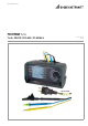
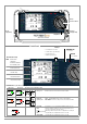
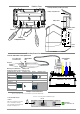
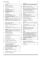
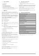
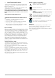
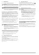
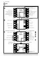
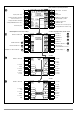
Table Of Contents
- 1 Scope of Delivery
- 2 Application
- 3 Safety Features and Precautions
- 4 Initial Start-Up
- 5 General Notes
- 5.1 Connecting the Instrument
- 5.2 Automatic Settings, Monitoring and Shut-Off
- 5.3 Measurement Value Display and Memory
- 5.4 Testing Earthing Contact Sockets for Correct Connection
- 5.5 Help Function
- 5.6 Setting Parameters or Limit Values using RCD Measurement as an Example
- 5.7 Freely Selectable Parameter Settings or Limit Values
- 5.8 2-Pole Measurement with Fast or Semiautomatic Polarity Reversal
- 6 Measuring Voltage and Frequency
- 7 Testing RCDs
- 8 Testing of Breaking Requirements for Overcurrent Protective Devices, Measurement of Loop Impedance and Determination of Short-Circuit Current (functions ZL-PE and IK)
- 9 Measuring Line Impedance (ZL-N function)
- 10 Earthing Resistance Measurement (RE function)
- 11 Measurement of Insulation Resistance
- 12 Measuring Low-Value Resistance up to 200 Ohm (protective conductor and equipotential bonding conductor)
- 13 Special Functions – EXTRA Switch Position
- 14 Database
- 15 Attaching the Test Probe Holder to the Carrying Strap
- 16 LED Indications, Mains Connections and Potential Differences
- 17 Characteristic Values
- 18 Maintenance
- 19 Appendix
- 19.1 Tables for Determining Maximum or Minimum Display Values in Consideration of Maximum Measuring Uncertainty
- 19.2 At which values should/must an RCD actually be tripped? Requirements for Residual Current Devices (RCDs)
- 19.3 Periodic Testing per DGUV Regulations 3 (formerly BGV A3) – Limit Values for Electrical Systems and Operating Equipment
- 19.4 Optional Accessories (not included)
- 19.5 List of Abbreviations and their Meanings
- 19.6 Keyword Index
- 19.7 Bibliography
- 20 Repair and Replacement Parts Service Calibration Center* and Rental Instrument Service
- 21 Recalibration
- 22 Product Support

GMC-I Messtechnik GmbH 3
LN
PE
L1L3L2
n.c.
Z550A Option
Battery Holder
Battery Compartment Lid
Battery Holder
Contacts
Battery
Contact
Spring
user interface
Batteries, Fuses
Measuring Connections
!
RS 232
Charger Socket, Interfaces
These connections are located under a protective rubber flap.
a b
Battery
Socket for Z502R charger
Caution!
Make sure no batteries are inserted
before connecting the charger.
The test instrument must remain off
during the charging process.
Fuses
Inserting the Battery Holder (side view)
USB Slave
for Connection to PC
Port for connecting Barcode/RFID reader
Assignment of Keys to Device or Remote Control
Measuring Function At Device Via Remote Control At Device Via Remote Control
Start measurement Tripping test
I∆N
IF
Measuring function Start measurement OFFSET
ZL-PE, ZL-N
RE
RLO, ∆U
RINS
Measurement Key for Measuring
Measuring Point Illumination
Point Illumination
Safety Collar
Test probe
Test Probe with Remote Control, Option Z550A
Optional Z503K
n.c.
Z503L
Compartment
Compartment Lid
Key