
User Manual
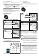
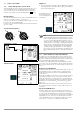
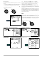
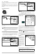
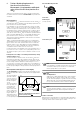
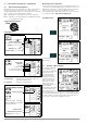
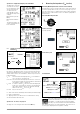
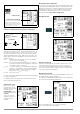
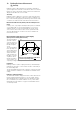
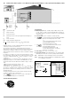
Table Of Contents
- 1 Scope of Delivery
- 2 Application
- 3 Safety Features and Precautions
- 4 Initial Start-Up
- 5 General Notes
- 5.1 Connecting the Instrument
- 5.2 Automatic Settings, Monitoring and Shut-Off
- 5.3 Measurement Value Display and Memory
- 5.4 Testing Earthing Contact Sockets for Correct Connection
- 5.5 Help Function
- 5.6 Setting Parameters or Limit Values using RCD Measurement as an Example
- 5.7 Freely Selectable Parameter Settings or Limit Values
- 5.8 2-Pole Measurement with Fast or Semiautomatic Polarity Reversal
- 6 Measuring Voltage and Frequency
- 7 Testing RCDs
- 8 Testing of Breaking Requirements for Overcurrent Protective Devices, Measurement of Loop Impedance and Determination of Short-Circuit Current (functions ZL-PE and IK)
- 9 Measuring Line Impedance (ZL-N function)
- 10 Earthing Resistance Measurement (RE function)
- 11 Measurement of Insulation Resistance
- 12 Measuring Low-Value Resistance up to 200 Ohm (protective conductor and equipotential bonding conductor)
- 13 Special Functions – EXTRA Switch Position
- 14 Database
- 15 Attaching the Test Probe Holder to the Carrying Strap
- 16 LED Indications, Mains Connections and Potential Differences
- 17 Characteristic Values
- 18 Maintenance
- 19 Appendix
- 19.1 Tables for Determining Maximum or Minimum Display Values in Consideration of Maximum Measuring Uncertainty
- 19.2 At which values should/must an RCD actually be tripped? Requirements for Residual Current Devices (RCDs)
- 19.3 Periodic Testing per DGUV Regulations 3 (formerly BGV A3) – Limit Values for Electrical Systems and Operating Equipment
- 19.4 Optional Accessories (not included)
- 19.5 List of Abbreviations and their Meanings
- 19.6 Keyword Index
- 19.7 Bibliography
- 20 Repair and Replacement Parts Service Calibration Center* and Rental Instrument Service
- 21 Recalibration
- 22 Product Support

GMC-I Messtechnik GmbH 29
10 Earthing Resistance Measurement
(R
E
function)
Earthing resistance R
E
is important for automatic shutdown in
system segments. It must have a low value in order to assure that
high short-circuit current flows and the system is shut down reli-
ably by the RCCB in the event of a fault.
Test Setup
Earthing resistance (R
E
) is the sum of the earth electrode’s dissi-
pation resistance and earth conductor resistance. Earthing resis-
tance is measured by applying an alternating current via the earth
conductor, the earth electrode and earth electrode resistance.
Measurement without Probe (mains powered earthing measure-
ment)
In many cases, especially in extremely built-up areas, it’s difficult,
or even impossible, to set a measuring probe. In such cases,
earthing resistance can be measured without a probe. In this
case, however, the resistance values for the operational earth
electrode R
B
and phase conductor L are also included in the
measurement results.
Measuring Method with Suppression of RCD Tripping
(mains powered earthing measurement)
The test instrument
generates a direct
current to this end,
which saturates the
RCCB’s magnetic
circuit.
The test instrument
then superimposes
a measuring current
which only demon-
strates half-waves
of like polarity. The
RCCB is no longer
capable of detect-
ing this measuring
current, and is con-
sequently not tripped during measurement.
Limit values
Earthing resistance (earth coupling resistance) is determined pri-
marily by the electrode’s contact surface and the conductivity of
the surrounding earth.
The specified limit value depends on the type of electrical system
and its shutdown conditions in consideration of maximum touch
voltage.
Evaluation of Measured Values
The maximum allowable displayed resistance values which assure
that the required earthing resistance is not exceeded, and for
which maximum device operating error has already been taken
into consideration (at nominal conditions of use), can be deter-
mined with the help of Table 2 on page 54. Intermediate values
can be interpolated.
Start
t1
t3
Measuring
t2
Operation
RCD Disabled!
t
I
F
/mA
Suppression of RCCB tripping for RCCBs which
are sensitive to pulsating current