
User Manual
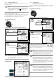
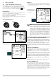
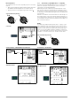
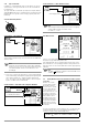
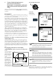
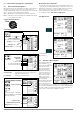
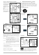
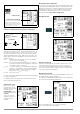
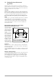
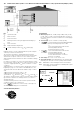
Table Of Contents
- 1 Scope of Delivery
- 2 Application
- 3 Safety Features and Precautions
- 4 Initial Start-Up
- 5 General Notes
- 5.1 Connecting the Instrument
- 5.2 Automatic Settings, Monitoring and Shut-Off
- 5.3 Measurement Value Display and Memory
- 5.4 Testing Earthing Contact Sockets for Correct Connection
- 5.5 Help Function
- 5.6 Setting Parameters or Limit Values using RCD Measurement as an Example
- 5.7 Freely Selectable Parameter Settings or Limit Values
- 5.8 2-Pole Measurement with Fast or Semiautomatic Polarity Reversal
- 6 Measuring Voltage and Frequency
- 7 Testing RCDs
- 8 Testing of Breaking Requirements for Overcurrent Protective Devices, Measurement of Loop Impedance and Determination of Short-Circuit Current (functions ZL-PE and IK)
- 9 Measuring Line Impedance (ZL-N function)
- 10 Earthing Resistance Measurement (RE function)
- 11 Measurement of Insulation Resistance
- 12 Measuring Low-Value Resistance up to 200 Ohm (protective conductor and equipotential bonding conductor)
- 13 Special Functions – EXTRA Switch Position
- 14 Database
- 15 Attaching the Test Probe Holder to the Carrying Strap
- 16 LED Indications, Mains Connections and Potential Differences
- 17 Characteristic Values
- 18 Maintenance
- 19 Appendix
- 19.1 Tables for Determining Maximum or Minimum Display Values in Consideration of Maximum Measuring Uncertainty
- 19.2 At which values should/must an RCD actually be tripped? Requirements for Residual Current Devices (RCDs)
- 19.3 Periodic Testing per DGUV Regulations 3 (formerly BGV A3) – Limit Values for Electrical Systems and Operating Equipment
- 19.4 Optional Accessories (not included)
- 19.5 List of Abbreviations and their Meanings
- 19.6 Keyword Index
- 19.7 Bibliography
- 20 Repair and Replacement Parts Service Calibration Center* and Rental Instrument Service
- 21 Recalibration
- 22 Product Support

28 GMC-I Messtechnik GmbH
Settings for Calculating Short-Circuit Current – Parameter I
K
Short-circuit current I
K
is used to test shutdown by means of an
overcurrent protective device. In order for an overcurrent protec-
tive device to be tripped on time, short-circuit current I
K
must be
greater than tripping current Ia (see table 6 in section 19.1). The
variants which can be selected with the “Limits” key have the fol-
lowing meanings:
I
K
: Ia The measured value displayed for I
K
is used without
any correction to calculate Z
L-PE
.
I
K
: Ia+∆% The measured value displayed for Z
L-PE
is corrected
by an amount equal to the test instrument’s measuring
uncertainty in order to calculate I
K
.
I
K
: 2/3 Z In order to calculate I
K
, the measured value displayed
for Z
L-PE
is corrected by an amount corresponding to
all possible deviations (these are defined in detail by
VDE 0100-60 as Z
s(m)
≤ 2/3 x U
0
/Ia).
I
K
: 3/4 Z Z
s(m)
≤ 3/4 x U
0
/Ia
I
K
Short-circuit current calculated by the instrument (at nominal voltage)
Z Fault loop impedance
Ia Tripping current (see data sheet for circuit breakers / fuses)
∆
%
Test instrument inherent error
Special case I
k
> I
kmax
If the short-circuit cur-
rent value does not lie
within the measured val-
ues defined in the
PROFITEST INTRO, this is
indicated by displaying
“>IK-max”.
In this case, manual
evaluation of the mea-
surement results is
required.
Measurement Cable Compensation
The resistance of the respectively connected measurement cable or the
country-specific measuring adapter must be compensated for each line
impedance measurement, i.e. it must be subtracted from the measure-
ment results as an offset. Proceed as described in section 4.5 under
„OFFSET RL-PE / RN-PE / RL-N“ on page 12 to this end in order to
ascertain offset values
RLPE-OFFSET
and
RNPE-OFFSET
Start Measurement
Display of U
L-N
(U
N
/ f
N
)
If the measured voltage value lies within a range of ±10% of the
respective nominal line voltage of 120 V, 230 V or 400 V, the
respectively corresponding nominal line voltage is displayed. In
the case of measured values outside of the ±10% tolerance, the
actual measured value is displayed.
Displaying the Fuse Table
After measurement has been performed, allowable fuse types can
be displayed by pressing the HELP key.
The table shows maximum allowable nominal current dependent
upon fuse type and breaking requirements.
Key: Ia = breaking current, I
K
= short-circuit current,
I
N
= nominal current, tA = tripping time
Semiautomatic measurement
See also section 5.8 regarding the AUTO
parameter. L-PE relationships are not
possible here. The neutral L-N relationship
is not offered during automatic sequenc-
ing to the right of the auto entry!
Polarity selection
Limit Value:
I
K
< limit value
LIMIT
I
K