
User Manual
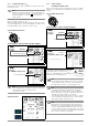
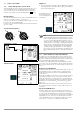
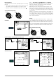
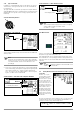
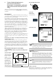
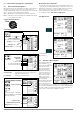
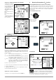
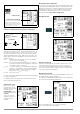
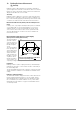
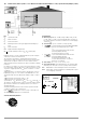
Table Of Contents
- 1 Scope of Delivery
- 2 Application
- 3 Safety Features and Precautions
- 4 Initial Start-Up
- 5 General Notes
- 5.1 Connecting the Instrument
- 5.2 Automatic Settings, Monitoring and Shut-Off
- 5.3 Measurement Value Display and Memory
- 5.4 Testing Earthing Contact Sockets for Correct Connection
- 5.5 Help Function
- 5.6 Setting Parameters or Limit Values using RCD Measurement as an Example
- 5.7 Freely Selectable Parameter Settings or Limit Values
- 5.8 2-Pole Measurement with Fast or Semiautomatic Polarity Reversal
- 6 Measuring Voltage and Frequency
- 7 Testing RCDs
- 8 Testing of Breaking Requirements for Overcurrent Protective Devices, Measurement of Loop Impedance and Determination of Short-Circuit Current (functions ZL-PE and IK)
- 9 Measuring Line Impedance (ZL-N function)
- 10 Earthing Resistance Measurement (RE function)
- 11 Measurement of Insulation Resistance
- 12 Measuring Low-Value Resistance up to 200 Ohm (protective conductor and equipotential bonding conductor)
- 13 Special Functions – EXTRA Switch Position
- 14 Database
- 15 Attaching the Test Probe Holder to the Carrying Strap
- 16 LED Indications, Mains Connections and Potential Differences
- 17 Characteristic Values
- 18 Maintenance
- 19 Appendix
- 19.1 Tables for Determining Maximum or Minimum Display Values in Consideration of Maximum Measuring Uncertainty
- 19.2 At which values should/must an RCD actually be tripped? Requirements for Residual Current Devices (RCDs)
- 19.3 Periodic Testing per DGUV Regulations 3 (formerly BGV A3) – Limit Values for Electrical Systems and Operating Equipment
- 19.4 Optional Accessories (not included)
- 19.5 List of Abbreviations and their Meanings
- 19.6 Keyword Index
- 19.7 Bibliography
- 20 Repair and Replacement Parts Service Calibration Center* and Rental Instrument Service
- 21 Recalibration
- 22 Product Support

GMC-I Messtechnik GmbH 27
Special Case: Suppressing Display of the Limit Value
The limit value cannot be
ascertained. The inspec-
tor is prompted to evalu-
ate the measured val-
ues himself, and to
acknowledge or reject
them with the help of the
softkeys.
Measurement passed:
✔ key
Measurement failed: X
key
The measured value can
only be saved after it has
been evaluated.
8.3 Settings for Calculating Short-Circuit Current –
Parameter I
K
Short-circuit current I
K
is used to test shutdown by means of an
overcurrent protective device. In order for an overcurrent protec-
tive device to be tripped on time, short-circuit current I
K
must be
greater than tripping current Ia (see table 6 in section 19.1). The
variants which can be selected with the “Limits” key have the fol-
lowing meanings:
I
K
: Ia The measured value displayed for I
K
is used without
any correction to calculate Z
L-PE
.
I
K
: Ia+∆% The measured value displayed for Z
L-PE
is corrected
by an amount equal to the test instrument’s measuring
uncertainty in order to calculate I
K
.
I
K
: 2/3 Z In order to calculate I
K
, the measured value displayed
for Z
L-PE
is corrected by an amount corresponding to
all possible deviations (these are defined in detail by
VDE 0100-60 as Z
s(m)
≤ 2/3 x U
0
/Ia).
I
K
: 3/4 Z Z
s(m)
≤ 3/4 x U
0
/Ia
I
K
Short-circuit current calculated by the instrument (at nominal voltage)
Z Fault loop impedance
Ia Tripping current (see data sheet for circuit breakers / fuses)
∆
%
Test instrument inherent error
Special case: I
k
> I
kmax
, see page 28.
See page 28 on accessing the fuse table via the
HELP
key.
9 Measuring Line Impedance (Z
L-N
function)
Measuring Method (internal line resistance measurement)
Line impedance Z
L-N
is measured by means of the same method
used for loop impedance Z
L-PE
(see section 8 on page 25). How-
ever, the current loop is completed via neutral conductor N rather
than protective conductor PE as is the case with loop impedance
measurement.
Select the Measuring Function
Schuko Connection
(country specific)
Connection: 2-pole
Set Parameters
Press the softkey shown at the left in order to switch
back and forth between the country-specific measur-
ing adapter, e.g. PRO-Schuko measuring adapter
(Z503K) / 3-pole measurement and the KS-PROFIT-
EST INTRO (Z503L) for 2-pole measurement. The selected con-
nection type is displayed inversely (white on black).
Limit Value:
I
K
< limit value
LIMIT
Z
L-N
Nom. current:
2 ... 160 A, 9999 A
Diameter: 1.5 to 70 sq. mm
Cable types: NY..., H07...
Number of wires:
1 to 10-strand
Tripping characteristics:
A, B/L, C/G, D, E, H, K, GL/GG & factor