
User Manual
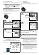
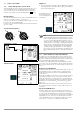
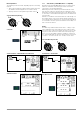
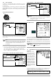
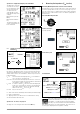
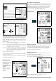
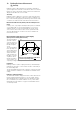
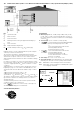
Table Of Contents
- 1 Scope of Delivery
- 2 Application
- 3 Safety Features and Precautions
- 4 Initial Start-Up
- 5 General Notes
- 5.1 Connecting the Instrument
- 5.2 Automatic Settings, Monitoring and Shut-Off
- 5.3 Measurement Value Display and Memory
- 5.4 Testing Earthing Contact Sockets for Correct Connection
- 5.5 Help Function
- 5.6 Setting Parameters or Limit Values using RCD Measurement as an Example
- 5.7 Freely Selectable Parameter Settings or Limit Values
- 5.8 2-Pole Measurement with Fast or Semiautomatic Polarity Reversal
- 6 Measuring Voltage and Frequency
- 7 Testing RCDs
- 8 Testing of Breaking Requirements for Overcurrent Protective Devices, Measurement of Loop Impedance and Determination of Short-Circuit Current (functions ZL-PE and IK)
- 9 Measuring Line Impedance (ZL-N function)
- 10 Earthing Resistance Measurement (RE function)
- 11 Measurement of Insulation Resistance
- 12 Measuring Low-Value Resistance up to 200 Ohm (protective conductor and equipotential bonding conductor)
- 13 Special Functions – EXTRA Switch Position
- 14 Database
- 15 Attaching the Test Probe Holder to the Carrying Strap
- 16 LED Indications, Mains Connections and Potential Differences
- 17 Characteristic Values
- 18 Maintenance
- 19 Appendix
- 19.1 Tables for Determining Maximum or Minimum Display Values in Consideration of Maximum Measuring Uncertainty
- 19.2 At which values should/must an RCD actually be tripped? Requirements for Residual Current Devices (RCDs)
- 19.3 Periodic Testing per DGUV Regulations 3 (formerly BGV A3) – Limit Values for Electrical Systems and Operating Equipment
- 19.4 Optional Accessories (not included)
- 19.5 List of Abbreviations and their Meanings
- 19.6 Keyword Index
- 19.7 Bibliography
- 20 Repair and Replacement Parts Service Calibration Center* and Rental Instrument Service
- 21 Recalibration
- 22 Product Support

GMC-I Messtechnik GmbH 25
8 Testing of Breaking Requirements for
Overcurrent Protective Devices,
Measurement of Loop Impedance and Determi-
nation of Short-Circuit Current (functions Z
L-PE
and I
K
)
Testing of overcurrent protective devices includes visual inspec-
tion and measurement. Use the PROFITEST INTRO to perform mea-
surements.
Measuring Method
Loop impedance Z
L-PE
is measured and short-circuit current I
K
is
ascertained in order to determine if the breaking requirements for
protective devices have been fulfilled.
Loop impedance is the resistance within the current loop (utility
station – phase conductor – protective conductor) when a short-
circuit to an exposed conductive part occurs (conductive connec-
tion between phase conductor and protective conductor). Short-
circuit current magnitude is determined by the loop impedance
value. Short-circuit current I
K
may not fall below a predetermined
value set forth by DIN VDE 0100, so that reliable breaking of the
protective device (fuse, automatic circuit breaker) is assured.
Thus the measured loop impedance value must be less than the
maximum allowable value.
Tables containing allowable display values for loop impedance
and minimum short-circuit current display values for ampere rat-
ings for various fuses and circuit breakers can be found in the
help texts and in section 19 beginning on page 54. Maximum
device error in accordance with VDE 0413 has been taken into
consideration in these tables. See also section 8.2.
In order to measure loop impedance Z
L-PE
, the instrument uses a
test current of 3.7 A to 7 A (60 to 550 V) depending on line volt-
age and line frequency. The test has a duration of max. 1200 ms
at 16 Hz.
If dangerous touch voltage occurs during measurement (> 50 V),
safety shut-down occurs.
The test instrument calculates short-circuit current I
K
based on
measured loop impedance
Z
L-PE
and line voltage. Short-circuit
current calculation is made with reference to nominal line voltage
for line voltages which lie within the nominal ranges for 120 V,
230 V and 400 V systems. If line voltage does not lie within these
nominal ranges, the instrument calculates short-circuit current I
K
based upon prevailing line voltage and measured loop impedance
Z
L-PE
.
Measuring Method with Suppression of RCD Tripping
The PROFITEST INTRO provides users with the opportunity of mea-
suring loop impedance within systems which are equipped with
RCCBs.
The test instrument
generates a direct
current to this end,
which saturates the
RCCB’s magnetic
circuit.
The test instrument
then superimposes
a measuring cur-
rent which only
demonstrates half-
waves of like polar-
ity. The RCCB is no
longer capable of
detecting this mea-
suring current, and
is consequently not tripped during measurement.
Select the Measuring Function
Connection:
Schuko/3-pole
(country specific)
Connection: 2-pole
Note
Loop impedance should be measured for each electrical
circuit at the farthest point, in order to ascertain maxi-
mum loop impedance for the system.
Note
Bias Magnetization
Suppression of RCD tripping by means of bias magneti-
zation with direct current is only possible via a country-
specific measuring adapter, e.g. PRO-Schuko measuring
adapter (Z503K) or the KS-PROFITEST INTRO (Z503L)
for 3-pole measurement (neutral conductor required).
Note
Observe national regulations, e.g. the necessity of con-
ducting measurements without regard for RCCBs in
Austria.
3-Phase Connections
Measurement of loop impedance to earth must be performed at
all three phase conductors (L1, L2, and L3) for the testing of over-
current protective devices at three phase outlets.
Start
t1 t3
Measuring
t2
Operation
RCD Disabled!
t
I
F
/mA
Suppression of RCCB tripping for RCCBs which are
sensitive to pulsating current
Z
L-PE