
User Manual
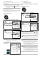
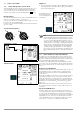
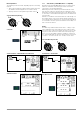
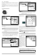
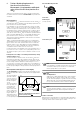
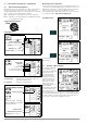
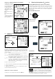
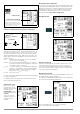
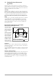
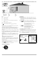
Table Of Contents
- 1 Scope of Delivery
- 2 Application
- 3 Safety Features and Precautions
- 4 Initial Start-Up
- 5 General Notes
- 5.1 Connecting the Instrument
- 5.2 Automatic Settings, Monitoring and Shut-Off
- 5.3 Measurement Value Display and Memory
- 5.4 Testing Earthing Contact Sockets for Correct Connection
- 5.5 Help Function
- 5.6 Setting Parameters or Limit Values using RCD Measurement as an Example
- 5.7 Freely Selectable Parameter Settings or Limit Values
- 5.8 2-Pole Measurement with Fast or Semiautomatic Polarity Reversal
- 6 Measuring Voltage and Frequency
- 7 Testing RCDs
- 8 Testing of Breaking Requirements for Overcurrent Protective Devices, Measurement of Loop Impedance and Determination of Short-Circuit Current (functions ZL-PE and IK)
- 9 Measuring Line Impedance (ZL-N function)
- 10 Earthing Resistance Measurement (RE function)
- 11 Measurement of Insulation Resistance
- 12 Measuring Low-Value Resistance up to 200 Ohm (protective conductor and equipotential bonding conductor)
- 13 Special Functions – EXTRA Switch Position
- 14 Database
- 15 Attaching the Test Probe Holder to the Carrying Strap
- 16 LED Indications, Mains Connections and Potential Differences
- 17 Characteristic Values
- 18 Maintenance
- 19 Appendix
- 19.1 Tables for Determining Maximum or Minimum Display Values in Consideration of Maximum Measuring Uncertainty
- 19.2 At which values should/must an RCD actually be tripped? Requirements for Residual Current Devices (RCDs)
- 19.3 Periodic Testing per DGUV Regulations 3 (formerly BGV A3) – Limit Values for Electrical Systems and Operating Equipment
- 19.4 Optional Accessories (not included)
- 19.5 List of Abbreviations and their Meanings
- 19.6 Keyword Index
- 19.7 Bibliography
- 20 Repair and Replacement Parts Service Calibration Center* and Rental Instrument Service
- 21 Recalibration
- 22 Product Support

24 GMC-I Messtechnik GmbH
7.3.4 Type G or R RCCB
In addition to standard RCCBs and selective RCDs, the special
characteristics of the type G RCCB can also be tested with the
test instrument.
The type G RCCB is an Austrian specialty and complies with the
ÖVE/ÖNORM E 8601 device standard. Erroneous tripping is min-
imized thanks to its greater current carrying capacity and short-
term delay.
Select the Measuring Function
Set Parameter – Type G/R (VSK)
Touch voltage and time to trip can be measured in the G/R-RCD
switch position.
Note
It must be observed that time to trip for type G RCCBs
may be as long as 1000 ms when measurement is made
at nominal residual current. Set the limit value corre-
spondingly.
➭ Then select 5 x I
∆N
in the menu (this is selected automatically
for the G/R setting) and repeat the tripping test beginning with
the positive half-wave at 0° and the negative half-wave at
180°. The longer of the two tripping times is decisive regard-
ing the condition of the tested RCCB.
Set the Parameter – Start with Positive or Negative Half-Wave
Set the Parameter – 5 Times Nominal Current
Note
The following restrictions apply to the selection of tripping
current multiples relative to nominal current:
500 mA: 1 x, 2 x I
∆N
Start Measurement
In both cases tripping time must be between 10 ms (minimum
delay time for type G RCCBs!) and 40 ms.
Type G RCCBs with other nominal residual current values must
be tested with the corresponding parameter setting under menu
item I
∆N
. In this case as well, the limit value must be appropriately
adjusted.
Note
The RCD parameter setting for selective RCCBs is not
suitable for type G RCCBs.
7.4 Testing Residual Current Circuit Breakers in TN-S Systems
Connection
RCCBs can only be
used in TN-S systems.
An RCCB would not
work in a TN-C system
because PE is directly
connected to the neu-
tral conductor in the out-
let (it does not bypass
the RCCB). This means
that residual current
would be returned via
the RCCB and would
not generate any differ-
ential current, which is
required in order to trip
the RCCB.
As a rule, the display for touch voltage is also 0.1 V, because the
nominal residual current of 30 mA together with minimal loop
resistance result in a very small voltage value:
I
∆N
Type 1:
180°: Start with negative half-wave
0°: Start with positive half-wave
Waveform:
Positive direct current
5 times tripping current
S
UI∆NR
E
I∆N• 1Ω 30mA⋅ 30mV 0 03V,== ==