
User Manual
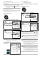
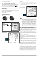
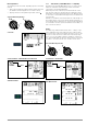
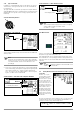
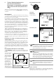
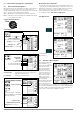
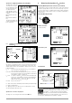
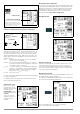
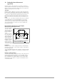
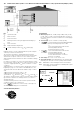
Table Of Contents
- 1 Scope of Delivery
- 2 Application
- 3 Safety Features and Precautions
- 4 Initial Start-Up
- 5 General Notes
- 5.1 Connecting the Instrument
- 5.2 Automatic Settings, Monitoring and Shut-Off
- 5.3 Measurement Value Display and Memory
- 5.4 Testing Earthing Contact Sockets for Correct Connection
- 5.5 Help Function
- 5.6 Setting Parameters or Limit Values using RCD Measurement as an Example
- 5.7 Freely Selectable Parameter Settings or Limit Values
- 5.8 2-Pole Measurement with Fast or Semiautomatic Polarity Reversal
- 6 Measuring Voltage and Frequency
- 7 Testing RCDs
- 8 Testing of Breaking Requirements for Overcurrent Protective Devices, Measurement of Loop Impedance and Determination of Short-Circuit Current (functions ZL-PE and IK)
- 9 Measuring Line Impedance (ZL-N function)
- 10 Earthing Resistance Measurement (RE function)
- 11 Measurement of Insulation Resistance
- 12 Measuring Low-Value Resistance up to 200 Ohm (protective conductor and equipotential bonding conductor)
- 13 Special Functions – EXTRA Switch Position
- 14 Database
- 15 Attaching the Test Probe Holder to the Carrying Strap
- 16 LED Indications, Mains Connections and Potential Differences
- 17 Characteristic Values
- 18 Maintenance
- 19 Appendix
- 19.1 Tables for Determining Maximum or Minimum Display Values in Consideration of Maximum Measuring Uncertainty
- 19.2 At which values should/must an RCD actually be tripped? Requirements for Residual Current Devices (RCDs)
- 19.3 Periodic Testing per DGUV Regulations 3 (formerly BGV A3) – Limit Values for Electrical Systems and Operating Equipment
- 19.4 Optional Accessories (not included)
- 19.5 List of Abbreviations and their Meanings
- 19.6 Keyword Index
- 19.7 Bibliography
- 20 Repair and Replacement Parts Service Calibration Center* and Rental Instrument Service
- 21 Recalibration
- 22 Product Support

GMC-I Messtechnik GmbH 23
Measuring Method
The following can be measured, depending upon the measuring
method:
•Time to trip t
A
: tripping test with nominal residual current I
∆N
(the PRCD-K must be tripped at 50% nominal current).
• Tripping current I
∆
for testing with rising residual current I
F
Select the Measuring Function
Connection
Set the Parameter – PRCD with Non-Linear Elements
Start Measurement
7.3.3 SRCD, PRCD-S (SCHUKOMAT, SIDOS or comparable)
RCCBs from the SCHUKOMAT SIDOS series, as well as others
which are of identical electrical design, must be tested after
selecting the corresponding parameter.
Monitoring of the PE conductor is performed for RCDs of this
type. The PE conductor is monitored by the summation current
transformer. If residual current flows from L to PE, tripping current
is cut in half, i.e. the RCCB must be tripped at 50% nominal resid-
ual current I
∆N
.
Whether or not PRCDs and selective RCDs are of like design can
be tested by means of the touch voltage U
I∆N
measurement. If a
touch voltage U
I∆N
of greater than 70 V is measured at the PRCD
of an otherwise error-free system, the PRCD more than likely con-
tains a non-linear element.
PRCD-S
The PRCD-S (portable residual current device – safety) is a spe-
cial, portable protective device with protective conductor detec-
tion or protective conductor monitoring. The device serves to pro-
tect persons from electrical accidents in the low-voltage range
(130 to 1000 V). The PRCD-S must be suitable for commercial
use, and is installed like an extension cable between an electrical
consumer – as a rule an electric tool – and the electric outlet.
Select the Measuring Function
Set Parameter – SRCD / PRCD
Start Measurement
I
∆N
Or
I
F
Type 1:
I
∆N
Or
I
F
Type 1: