
User Manual
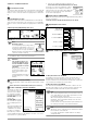
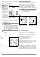
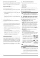
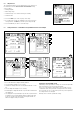
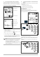
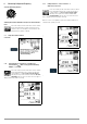
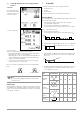
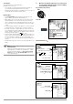
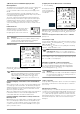
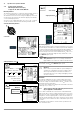
Table Of Contents
- 1 Scope of Delivery
- 2 Application
- 3 Safety Features and Precautions
- 4 Initial Start-Up
- 5 General Notes
- 5.1 Connecting the Instrument
- 5.2 Automatic Settings, Monitoring and Shut-Off
- 5.3 Measurement Value Display and Memory
- 5.4 Testing Earthing Contact Sockets for Correct Connection
- 5.5 Help Function
- 5.6 Setting Parameters or Limit Values using RCD Measurement as an Example
- 5.7 Freely Selectable Parameter Settings or Limit Values
- 5.8 2-Pole Measurement with Fast or Semiautomatic Polarity Reversal
- 6 Measuring Voltage and Frequency
- 7 Testing RCDs
- 8 Testing of Breaking Requirements for Overcurrent Protective Devices, Measurement of Loop Impedance and Determination of Short-Circuit Current (functions ZL-PE and IK)
- 9 Measuring Line Impedance (ZL-N function)
- 10 Earthing Resistance Measurement (RE function)
- 11 Measurement of Insulation Resistance
- 12 Measuring Low-Value Resistance up to 200 Ohm (protective conductor and equipotential bonding conductor)
- 13 Special Functions – EXTRA Switch Position
- 14 Database
- 15 Attaching the Test Probe Holder to the Carrying Strap
- 16 LED Indications, Mains Connections and Potential Differences
- 17 Characteristic Values
- 18 Maintenance
- 19 Appendix
- 19.1 Tables for Determining Maximum or Minimum Display Values in Consideration of Maximum Measuring Uncertainty
- 19.2 At which values should/must an RCD actually be tripped? Requirements for Residual Current Devices (RCDs)
- 19.3 Periodic Testing per DGUV Regulations 3 (formerly BGV A3) – Limit Values for Electrical Systems and Operating Equipment
- 19.4 Optional Accessories (not included)
- 19.5 List of Abbreviations and their Meanings
- 19.6 Keyword Index
- 19.7 Bibliography
- 20 Repair and Replacement Parts Service Calibration Center* and Rental Instrument Service
- 21 Recalibration
- 22 Product Support

20 GMC-I Messtechnik GmbH
7.2 Special Tests for Systems and RCDs
7.2.1 Testing Systems and RCCBs
with Rising Residual Current (AC)
for Type AC, A/F, B/B+ and EV, MI RCDs
Measuring Method
The instrument generates a continuously rising residual current of
(0.3 ... 1.3) • I
∆N
within the system for the testing of RCDs.
The instrument stores the touch voltage and tripping current val-
ues which were measured at the moment tripping of the RCCB
occurred, and displays them.
One of the touch voltage limit values, U
L
=25V or U
L
=50/65V,
can be selected for measurement with rising residual current.
Select the Measuring Function
Connection
Setting Parameters for I
F
Start Measurement
Measuring Sequence
After the measuring sequence has been started, the test current
generated by the instrument is continuously increased starting at
0.3 times nominal residual current, until the RCCB is tripped. This
can be observed by viewing gradual filling of the triangle at I∆.
If touch voltage reaches the selected limit value (U
L
=65V, 50V
or 25 V) before the RCCB is tripped, safety shut-down occurs.
The LIMIT LED lights up red.
Note
Safety Shut-down: At up to 70 V, a safety shut-down is
tripped within 3 seconds in accordance with IEC 61010.
If the RCCB is not tripped before the rising current reaches nomi-
nal residual current I
∆N
, the LIMIT LED lights up red.
Attention!
!
If bias current is present within the system during mea-
surement, it’s superimposed onto the residual current
which is generated by the instrument and influences
measured values for touch voltage and tripping current.
See also section 7.1.
Evaluation
According to DIN VDE 0100-600, rising residual current must,
however, be used for measurements in the evaluation of RCDs,
and touch voltage at nominal residual current I
∆N
must be calcu-
lated from the measured values.
The faster, more simple measuring method should thus be taken
advantage of (see section 7.1).
7.2.2 Testing Systems and RCCBs with Rising Residual Current
(AC) for Type B/B+ and EV, MI RCDs
In accordance with VDE 0413-6, it must be substantiated that,
with smooth direct current, residual operating current is no more
than twice the value of rated residual current I
∆N
. A continuously
rising direct current, beginning with 0.2 times rated residual cur-
rent I
∆N
, must be applied to this end. If current rise is linear, rising
current may not exceed twice the value of I
∆N
within a period of 5
seconds.
Testing with smoothed direct current must be possible in both
test current directions.
I
F
Nom. res. current:
10 ... 500 mA
Type 1:
RCD, SRCD, PRCD etc.
Nominal current: 6 ... 125 A
Type 2: AC , A/F , B/B+ *,
EV/MI, EV/MI
* Type B/B+/EV/MI =
AC/DC sensitive
Waveform:
Positive direct current
negative half-wave
positive half-wave
Touch voltage:
Tripping limit values: