
User Manual
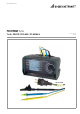
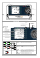
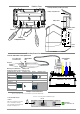
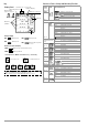
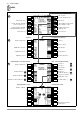
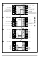
Table Of Contents
- 1 Scope of Delivery
- 2 Application
- 3 Safety Features and Precautions
- 4 Initial Start-Up
- 5 General Notes
- 5.1 Connecting the Instrument
- 5.2 Automatic Settings, Monitoring and Shut-Off
- 5.3 Measurement Value Display and Memory
- 5.4 Testing Earthing Contact Sockets for Correct Connection
- 5.5 Help Function
- 5.6 Setting Parameters or Limit Values using RCD Measurement as an Example
- 5.7 Freely Selectable Parameter Settings or Limit Values
- 5.8 2-Pole Measurement with Fast or Semiautomatic Polarity Reversal
- 6 Measuring Voltage and Frequency
- 7 Testing RCDs
- 8 Testing of Breaking Requirements for Overcurrent Protective Devices, Measurement of Loop Impedance and Determination of Short-Circuit Current (functions ZL-PE and IK)
- 9 Measuring Line Impedance (ZL-N function)
- 10 Earthing Resistance Measurement (RE function)
- 11 Measurement of Insulation Resistance
- 12 Measuring Low-Value Resistance up to 200 Ohm (protective conductor and equipotential bonding conductor)
- 13 Special Functions – EXTRA Switch Position
- 14 Database
- 15 Attaching the Test Probe Holder to the Carrying Strap
- 16 LED Indications, Mains Connections and Potential Differences
- 17 Characteristic Values
- 18 Maintenance
- 19 Appendix
- 19.1 Tables for Determining Maximum or Minimum Display Values in Consideration of Maximum Measuring Uncertainty
- 19.2 At which values should/must an RCD actually be tripped? Requirements for Residual Current Devices (RCDs)
- 19.3 Periodic Testing per DGUV Regulations 3 (formerly BGV A3) – Limit Values for Electrical Systems and Operating Equipment
- 19.4 Optional Accessories (not included)
- 19.5 List of Abbreviations and their Meanings
- 19.6 Keyword Index
- 19.7 Bibliography
- 20 Repair and Replacement Parts Service Calibration Center* and Rental Instrument Service
- 21 Recalibration
- 22 Product Support

2 GMC-I Messtechnik GmbH
LCD Panel
Setup Menu
Rotary
Selector Switch
Guide for
Carrying Strap
Guide for
Carrying Strap
MEM:Key for
memory functions
ESC: Return from
submenu /
Activate instrument
from standby state
Control Panel
Fixed Function Keys
MAINS/NETZ LED
→ see below
I∆
N
: Triggering key /
compensation (offset)
HELP: Access context
sensitive help
START:Switch on /
start measurement
Softkeys
• Parameter selection
• Limit value specification
• Entry functions
• Memory functions
LED Indications (see also section 16)
LED Case A LED Case B
LCD Case A LCD Case B
Function – Cause
A Lights up green: Correct connection, measurement enabled
B Blinks green: Neutral conductor not connected, measurement enabled
A
Lights up orange:
2 different phases active (no neutral conductor at mains), meas. enabled
B Blinks red: I∆N, IF , ZL-PE, ZL-N, RE: No line voltage or PE interrupted
C Lights up red: RINS and RLO: Interference voltage detected, measurement disabled
– UI∆, UI∆N:
Touch voltage > 25 or 50 V, measurement disabled: display: U.PE > UL!
– I∆N: During the tripping test with I
N
, the RCD is not tripped within 400 ms
(1000 ms for selective RCCBs of type RCD S).
– IF : With rising residual current, the RCD is not tripped before reaching I
N
.
– After safety shutdown
– RLO
:
The permissible (selected) limit value has been exceeded.
– RINS, RE(INS)
:
The permissible (selected) limit value has been exceeded.
Mains
Green
Mains
Blinks green
N
PE
L
N
PE
L
x
Mains
Orange
Mains
Blinks red
N
PE
L
N
PE
L
N
PE
L
x
LIMIT
Red
Limit LED
→ see below