
User Manual
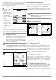
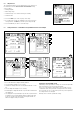
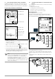
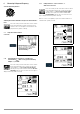
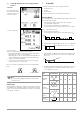
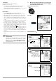
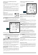
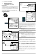
Table Of Contents
- 1 Scope of Delivery
- 2 Application
- 3 Safety Features and Precautions
- 4 Initial Start-Up
- 5 General Notes
- 5.1 Connecting the Instrument
- 5.2 Automatic Settings, Monitoring and Shut-Off
- 5.3 Measurement Value Display and Memory
- 5.4 Testing Earthing Contact Sockets for Correct Connection
- 5.5 Help Function
- 5.6 Setting Parameters or Limit Values using RCD Measurement as an Example
- 5.7 Freely Selectable Parameter Settings or Limit Values
- 5.8 2-Pole Measurement with Fast or Semiautomatic Polarity Reversal
- 6 Measuring Voltage and Frequency
- 7 Testing RCDs
- 8 Testing of Breaking Requirements for Overcurrent Protective Devices, Measurement of Loop Impedance and Determination of Short-Circuit Current (functions ZL-PE and IK)
- 9 Measuring Line Impedance (ZL-N function)
- 10 Earthing Resistance Measurement (RE function)
- 11 Measurement of Insulation Resistance
- 12 Measuring Low-Value Resistance up to 200 Ohm (protective conductor and equipotential bonding conductor)
- 13 Special Functions – EXTRA Switch Position
- 14 Database
- 15 Attaching the Test Probe Holder to the Carrying Strap
- 16 LED Indications, Mains Connections and Potential Differences
- 17 Characteristic Values
- 18 Maintenance
- 19 Appendix
- 19.1 Tables for Determining Maximum or Minimum Display Values in Consideration of Maximum Measuring Uncertainty
- 19.2 At which values should/must an RCD actually be tripped? Requirements for Residual Current Devices (RCDs)
- 19.3 Periodic Testing per DGUV Regulations 3 (formerly BGV A3) – Limit Values for Electrical Systems and Operating Equipment
- 19.4 Optional Accessories (not included)
- 19.5 List of Abbreviations and their Meanings
- 19.6 Keyword Index
- 19.7 Bibliography
- 20 Repair and Replacement Parts Service Calibration Center* and Rental Instrument Service
- 21 Recalibration
- 22 Product Support

GMC-I Messtechnik GmbH 19
1) Measuring Touch Current Without Tripping the RCD
Measuring Method
The instrument uses a measuring current of only ⅓ nominal resid-
ual current for the determination of touch voltage U
I∆N
which
occurs at nominal residual current. This prevents tripping of the
RCCB.
This measuring method is especially advantageous, because
touch voltage can be measured quickly and easily at any electrical
outlet without tripping the RCCB.
The usual, complex measuring method involving testing for the
proper functioning of the RCD at a given point, and subsequent
substantiation that all other systems components requiring pro-
tection are reliably connected at low resistance values to the
selected measuring point via the PE conductor, is made unneces-
sary.
N-PE Reversal Test
Additional testing is conducted in order to
determine whether or not N and PE are
reversed. The pop-up window shown at
the right appears in the event of reversal.
Attention!
!
In order to prevent the loss of data in data processing
systems, perform a data backup before starting the
measurement and switch off all consumers.
Start Measurement
Amongst other values, touch voltage U
I∆N
and calculated earthing
resistance R
E
appear at the display panel.
Note
The measured earthing resistance value R
E
is acquired
with very little current. More accurate results can be
obtained with the selector switch in the R
E
position.
The DC + function can be selected here for sys-
tems with RCCBs.
Unintentional Tripping of the RCD due to Bias Current within the
System
If bias currents should occur, they can be measured with the help
of a clamp type current transformer. The RCCB may be tripped
during the testing of touch voltage if extremely large bias currents
are present within the system, or if a test current was selected
which is too great for the RCCB.
After touch voltage has been measured, testing can be performed
to determine whether or not the RCCB is tripped within the
selected time limit values at nominal residual current.
Unintentional Tripping of the RCD due to Leakage Current in the
Measuring Circuit
Measurement of touch voltage with 30% nominal residual current
does not normally trip an RCCB. However, the trip limit may be
exceeded as a result of leakage current in the measuring circuit,
e.g. due to interconnected consumers with EMC circuit, e.g. fre-
quency converters or PCs.
2) Tripping Test after the Measurement of Touch Voltage
➭
Press the I
∆
N
key
The tripping test need
only be performed at
one measuring point for
each RCCB.
If the RCCB is not tripped at nominal residual current, the MAINS/NETZ
LED blinks red (line voltage disconnected) and, amongst other val-
ues, time to trip t
a
and earthing resistance R
E
appear at the dis-
play panel.
If the RCCB is not tripped at nominal residual current, the LIMIT LED
lights up red.
Touch Voltage Too High
If touch voltage U
I∆N
, which has been measured with ⅓ nominal
residual current I
∆N
and extrapolated to I
∆N
, is > 50 V (> 25 V), the
LIMIT LED lights up red.
If touch voltage U
I∆N
exceeds 50 V (25 V) during the measuring
sequence, safety shut-down occurs.
Note
Safety Shut-down: At up to 70 V, a safety shut-down is
tripped within 3 seconds in accordance with IEC 61010.
Touch voltages of up to 70 V are displayed. If the value is greater
than 70 V, U
I∆N
> 70 V is displayed.
Limit Values for Allowable, Continuous Touch Voltage
The limit for allowable, continuous touch voltage is equal to
U
L
= 50 V for alternating voltages (international agreement).
Lower values have been established for special applications
(e.g. medical applications: U
L
=25V).
Attention!
!
If touch voltage is too high, or if the RCCB is not tripped,
the system must be repaired (e.g. earthing resistance is
too high, defective RCCB etc.)!
3-Phase Connections
For proper RCD testing at three-phase connections, the tripping
test must be conducted for one of the three phase conductors
(L1, L2 or L3).
Inductive Power Consumers
Voltage peaks may occur within the measuring circuit if inductive
consumers are shut down during an RCCB trip test. If this is the
case, the test instrument might not display any measured value
(– – –). If this message appears, switch all consumers off before
performing the trip test. In extreme cases, one of the fuses in the
test instrument may blow, and/or the test instrument may be
damaged.