
User Manual
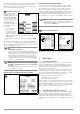
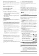
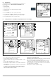
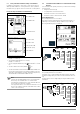
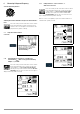
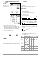
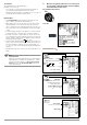
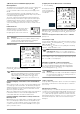
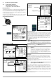
Table Of Contents
- 1 Scope of Delivery
- 2 Application
- 3 Safety Features and Precautions
- 4 Initial Start-Up
- 5 General Notes
- 5.1 Connecting the Instrument
- 5.2 Automatic Settings, Monitoring and Shut-Off
- 5.3 Measurement Value Display and Memory
- 5.4 Testing Earthing Contact Sockets for Correct Connection
- 5.5 Help Function
- 5.6 Setting Parameters or Limit Values using RCD Measurement as an Example
- 5.7 Freely Selectable Parameter Settings or Limit Values
- 5.8 2-Pole Measurement with Fast or Semiautomatic Polarity Reversal
- 6 Measuring Voltage and Frequency
- 7 Testing RCDs
- 8 Testing of Breaking Requirements for Overcurrent Protective Devices, Measurement of Loop Impedance and Determination of Short-Circuit Current (functions ZL-PE and IK)
- 9 Measuring Line Impedance (ZL-N function)
- 10 Earthing Resistance Measurement (RE function)
- 11 Measurement of Insulation Resistance
- 12 Measuring Low-Value Resistance up to 200 Ohm (protective conductor and equipotential bonding conductor)
- 13 Special Functions – EXTRA Switch Position
- 14 Database
- 15 Attaching the Test Probe Holder to the Carrying Strap
- 16 LED Indications, Mains Connections and Potential Differences
- 17 Characteristic Values
- 18 Maintenance
- 19 Appendix
- 19.1 Tables for Determining Maximum or Minimum Display Values in Consideration of Maximum Measuring Uncertainty
- 19.2 At which values should/must an RCD actually be tripped? Requirements for Residual Current Devices (RCDs)
- 19.3 Periodic Testing per DGUV Regulations 3 (formerly BGV A3) – Limit Values for Electrical Systems and Operating Equipment
- 19.4 Optional Accessories (not included)
- 19.5 List of Abbreviations and their Meanings
- 19.6 Keyword Index
- 19.7 Bibliography
- 20 Repair and Replacement Parts Service Calibration Center* and Rental Instrument Service
- 21 Recalibration
- 22 Product Support

GMC-I Messtechnik GmbH 17
6.2 3-Phase Measurement (line-to-line voltage) and Phase
Sequence
Connection
The included measure-
ment cables (Z503L) are
required in order to con-
nect the instrument.
➭ Press softkey U3~.
A clockwise phase
sequence is required at all 3-phase electrical outlets.
• Measurement instrument connection is usually problematic
with CEE outlets due to contact problems.
Measurements can be executed quickly and reliably without
contact problems with the help of the Z500A variable plug
adapter set available from GMC.
• Connection for 3-wire measurement: L1-L2-L3 at plug in
clockwise direction as of PE socket
Direction of rotation is indicated by means of the following dis-
plays:
Note
See section 16 regarding all indications for the mains
connection test.
Voltage polarity
If the installation of single-pole switches to the neutral conductor
is prohibited by the standards, voltage polarity must be tested in
order to assure that all existing single-pole switches are installed
to the phase conductors.
7 Testing RCDs
Testing of residual current devices (RCDs) includes:
• Visual inspection
•Testing
• Measurement
Use the test instrument for testing and measurement.
Measuring Method
The following must be substantiated by generating a fault current
downstream from the RCD:
• That the RCD is tripped no later than upon reaching
its nominal fault current value
• That continuously allowable touch voltage value
U
L
agreed upon for the respective system is not exceeded
This is achieved by means of:
• Touch voltage measurement,
10 measurements with full-waves and extrapolation of I
∆N
• Substantiation of tripping within 400 ms or 200 ms with I
∆N
• Substantiation of tripping current with rising residual current
This value must be between 50% and 100% of I
∆N
(usually
about 70%).
• No premature tripping with the test instrument, because test-
ing is begun with 30% residual current (if no bias current
occurs within the system)
Clockwise
Counterclockwise
RCD/FI
Table
Differential
Current Waveform
Correct RCD/RCCB Function
Type AC Type A/F
Type B/B+ Type EV/MI
Alternating
current
Suddenly occurring
✔✔✔✔
Slowly rising
Pulsating
direct current
Suddenly occurring
✔✔✔
Slowly rising
Direct
current
✔✔
Direct
current
up to 6 mA
✔
I
∆N
3
--------
I
∆N
(measurement for up to 1000 ms)
t
a
I
a
t