
User Manual
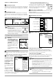
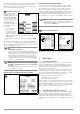
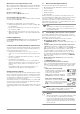
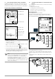
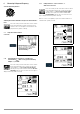
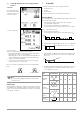
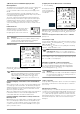
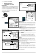
Table Of Contents
- 1 Scope of Delivery
- 2 Application
- 3 Safety Features and Precautions
- 4 Initial Start-Up
- 5 General Notes
- 5.1 Connecting the Instrument
- 5.2 Automatic Settings, Monitoring and Shut-Off
- 5.3 Measurement Value Display and Memory
- 5.4 Testing Earthing Contact Sockets for Correct Connection
- 5.5 Help Function
- 5.6 Setting Parameters or Limit Values using RCD Measurement as an Example
- 5.7 Freely Selectable Parameter Settings or Limit Values
- 5.8 2-Pole Measurement with Fast or Semiautomatic Polarity Reversal
- 6 Measuring Voltage and Frequency
- 7 Testing RCDs
- 8 Testing of Breaking Requirements for Overcurrent Protective Devices, Measurement of Loop Impedance and Determination of Short-Circuit Current (functions ZL-PE and IK)
- 9 Measuring Line Impedance (ZL-N function)
- 10 Earthing Resistance Measurement (RE function)
- 11 Measurement of Insulation Resistance
- 12 Measuring Low-Value Resistance up to 200 Ohm (protective conductor and equipotential bonding conductor)
- 13 Special Functions – EXTRA Switch Position
- 14 Database
- 15 Attaching the Test Probe Holder to the Carrying Strap
- 16 LED Indications, Mains Connections and Potential Differences
- 17 Characteristic Values
- 18 Maintenance
- 19 Appendix
- 19.1 Tables for Determining Maximum or Minimum Display Values in Consideration of Maximum Measuring Uncertainty
- 19.2 At which values should/must an RCD actually be tripped? Requirements for Residual Current Devices (RCDs)
- 19.3 Periodic Testing per DGUV Regulations 3 (formerly BGV A3) – Limit Values for Electrical Systems and Operating Equipment
- 19.4 Optional Accessories (not included)
- 19.5 List of Abbreviations and their Meanings
- 19.6 Keyword Index
- 19.7 Bibliography
- 20 Repair and Replacement Parts Service Calibration Center* and Rental Instrument Service
- 21 Recalibration
- 22 Product Support

16 GMC-I Messtechnik GmbH
6 Measuring Voltage and Frequency
Select the Measuring Function
Switching Back and Forth Between Single and 3-Phase Measure-
ment
Press the softkey shown at the left in order to switch
back and forth between single and 3-phase mea-
surement. The selected phase measurement is dis-
played inversely (white on black).
6.1 Single-Phase Measurement
Connection
6.1.1 Voltage Between L and N (U
L-N
),
L and PE
(U
L-PE
)
a
nd N and PE
(U
N-PE
) with Country-Specific Measuring
Adapter, e.g. SCHUKO
Press the softkey shown at the left in order to switch
back and forth between the country-specific mea-
suring adapter, e.g. PRO-Schuko measuring adapter
(Z503K), and 2-pole measurement with the KS-PROF-
ITEST INTRO (Z503L). The selected connection type is
displayed inversely (white on black).
6.1.2 Voltage Between L – PE, N – PE and L – L
with 2-Pole Connection
Press the softkey shown at the left in order to switch
back and forth between the country-specific mea-
suring adapter, e.g. PRO-Schuko measuring adapter
(Z503K), and 2-pole measurement with the KS-
PROFITEST INTRO (Z503L). The selected connection
type is displayed inversely (white on black).
Refer to section 5.8 regarding 2-pole measurement with fast or
semiautomatic polarity reversal.
U
2
1