
User Manual
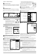
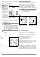
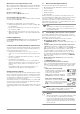
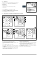
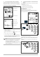
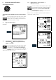
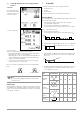
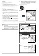
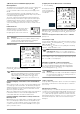
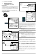
Table Of Contents
- 1 Scope of Delivery
- 2 Application
- 3 Safety Features and Precautions
- 4 Initial Start-Up
- 5 General Notes
- 5.1 Connecting the Instrument
- 5.2 Automatic Settings, Monitoring and Shut-Off
- 5.3 Measurement Value Display and Memory
- 5.4 Testing Earthing Contact Sockets for Correct Connection
- 5.5 Help Function
- 5.6 Setting Parameters or Limit Values using RCD Measurement as an Example
- 5.7 Freely Selectable Parameter Settings or Limit Values
- 5.8 2-Pole Measurement with Fast or Semiautomatic Polarity Reversal
- 6 Measuring Voltage and Frequency
- 7 Testing RCDs
- 8 Testing of Breaking Requirements for Overcurrent Protective Devices, Measurement of Loop Impedance and Determination of Short-Circuit Current (functions ZL-PE and IK)
- 9 Measuring Line Impedance (ZL-N function)
- 10 Earthing Resistance Measurement (RE function)
- 11 Measurement of Insulation Resistance
- 12 Measuring Low-Value Resistance up to 200 Ohm (protective conductor and equipotential bonding conductor)
- 13 Special Functions – EXTRA Switch Position
- 14 Database
- 15 Attaching the Test Probe Holder to the Carrying Strap
- 16 LED Indications, Mains Connections and Potential Differences
- 17 Characteristic Values
- 18 Maintenance
- 19 Appendix
- 19.1 Tables for Determining Maximum or Minimum Display Values in Consideration of Maximum Measuring Uncertainty
- 19.2 At which values should/must an RCD actually be tripped? Requirements for Residual Current Devices (RCDs)
- 19.3 Periodic Testing per DGUV Regulations 3 (formerly BGV A3) – Limit Values for Electrical Systems and Operating Equipment
- 19.4 Optional Accessories (not included)
- 19.5 List of Abbreviations and their Meanings
- 19.6 Keyword Index
- 19.7 Bibliography
- 20 Repair and Replacement Parts Service Calibration Center* and Rental Instrument Service
- 21 Recalibration
- 22 Product Support

14 GMC-I Messtechnik GmbH
5.5 Help Function
The following information can be displayed for each switch posi-
tion and basic function after it has been selected with the rotary
selector switch:
• Wiring diagram
• Measuring range
• Nominal range of use and measuring uncertainty
• Nominal value
➭ Press the HELP key in order to query online help.
➭ If several pages of help are available for the respective mea-
suring function, the HELP key must be pressed repeatedly.
➭ Press the ESC key in order to exit online help.
5.6 Setting Parameters or Limit Values using RCD Measurement as an Example
1 Access the submenu for setting the desired parameter.
2 Select a parameter using the ↑ or ↓ scroll key.
3 Switch to the setting menu for the selected parameter with the → scroll
key.
4 Select a setting value using the ↑ or ↓ scroll key.
5 Acknowledge the setting value with the ↵ key. This value is transferred to
the setting menu.
6 The setting value is not permanently accepted for the respective measure-
ment until ✓ is pressed, after which the display is returned to the main
menu. You can return to the main menu by pressing ESC instead of ✓,
without accepting the newly selected value.
Parameter Lock (plausibility check)
Individually selected parameter settings are checked for plausibil-
ity before transfer to the measurement window.
If you select a parameter setting which doesn’t make sense in
combination with other parameter settings which have already
been entered, it’s not accepted. The previously selected parame-
ter setting remains unchanged.
Remedy: Select another parameter setting.
1
2
2
3
4
4
5
6
2
4
3
5
6