
User Manual
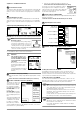
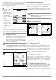
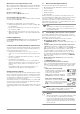
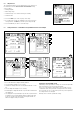
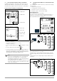
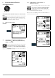
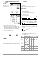
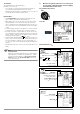
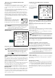
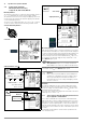
Table Of Contents
- 1 Scope of Delivery
- 2 Application
- 3 Safety Features and Precautions
- 4 Initial Start-Up
- 5 General Notes
- 5.1 Connecting the Instrument
- 5.2 Automatic Settings, Monitoring and Shut-Off
- 5.3 Measurement Value Display and Memory
- 5.4 Testing Earthing Contact Sockets for Correct Connection
- 5.5 Help Function
- 5.6 Setting Parameters or Limit Values using RCD Measurement as an Example
- 5.7 Freely Selectable Parameter Settings or Limit Values
- 5.8 2-Pole Measurement with Fast or Semiautomatic Polarity Reversal
- 6 Measuring Voltage and Frequency
- 7 Testing RCDs
- 8 Testing of Breaking Requirements for Overcurrent Protective Devices, Measurement of Loop Impedance and Determination of Short-Circuit Current (functions ZL-PE and IK)
- 9 Measuring Line Impedance (ZL-N function)
- 10 Earthing Resistance Measurement (RE function)
- 11 Measurement of Insulation Resistance
- 12 Measuring Low-Value Resistance up to 200 Ohm (protective conductor and equipotential bonding conductor)
- 13 Special Functions – EXTRA Switch Position
- 14 Database
- 15 Attaching the Test Probe Holder to the Carrying Strap
- 16 LED Indications, Mains Connections and Potential Differences
- 17 Characteristic Values
- 18 Maintenance
- 19 Appendix
- 19.1 Tables for Determining Maximum or Minimum Display Values in Consideration of Maximum Measuring Uncertainty
- 19.2 At which values should/must an RCD actually be tripped? Requirements for Residual Current Devices (RCDs)
- 19.3 Periodic Testing per DGUV Regulations 3 (formerly BGV A3) – Limit Values for Electrical Systems and Operating Equipment
- 19.4 Optional Accessories (not included)
- 19.5 List of Abbreviations and their Meanings
- 19.6 Keyword Index
- 19.7 Bibliography
- 20 Repair and Replacement Parts Service Calibration Center* and Rental Instrument Service
- 21 Recalibration
- 22 Product Support

GMC-I Messtechnik GmbH 13
Measurement of Touch Voltage via Finger Contact
When a measurement is started and if you touch the
ON/START key
with your finger, the test instrument detects whether or not dan-
gerous touch voltage Ub is present at the PE terminal relative to
ground.
Error in the U Switch Position:
PE appears and the LIMIT LED lights up red.
Error in All Switch Positions Other than U:
The test instrument disables the measurement and the following
message appears: U.PE > UL!
Prerequisites for reliable finger contact measurement:
1 Nothing is plugged into the interfaces and the charging cable
is not plugged in.
2 Based on his standing surface, the user has an earth resis-
tance of R.eb < 1 MΩ.
3 While starting the measurement, the user touches the “
ON/
START
” key with the full surface of an unprotected finger with
direct skin contact.
Insufficient Supply Voltage
If (rechargeable) battery voltage falls below the allowable limit value
the instrument cannot be switched on, or it is immediately
switched off.
Conditions Resulting in Disabling and Abortion of Measurements
The measurement is interrupted automatically or the measuring
sequence is blocked (except for voltage measuring ranges and
phase sequence testing) in the event of:
• Impermissible line voltages (< 60 V, > 253 V / > 330 V /
> 440 V or > 550 V) for measurements which require line volt-
age
• Interference voltage during insulation resistance or low resis-
tance measurements
• Overheating at the instrument.
As a rule, excessive temperatures only occur after approxi-
mately 50 measurement sequences at intervals of 5 seconds,
when the rotary selector switch is set to the Z
L-PE
or Z
L-N
position.
If an attempt is made to start a measuring sequence, an
appropriate message appears at the display panel.
Automatic Instrument Shutdown
The instrument only switches itself off automatically after comple-
tion of an automatic measuring sequence, and after the predeter-
mined on-time has expired (see section 4.2). On-time is reset to
its original value as defined in the setup menu as soon as any key
or the rotary selector switch is activated.
The instrument remains on for approximately 75 seconds in addi-
tion to the preset on-time for measurements with rising residual
current in systems with selective RCDs.
The instrument always shuts itself off automatically, unless the fol-
lowing setting has been selected in SETUP: “>>>>>” (continuous
on).
5.3 Measurement Value Display and Memory
The following items appear at the display panel:
• Measured values with abbreviations and units of measure
• Selected function
• Nominal voltage
• Nominal frequency
• Error messages
Measurement values for automatic measuring sequences are
stored and displayed as digital values until the next measurement
sequence is started, or until automatic shut-off occurs.
If the upper range limit is exceeded, the upper limit value is dis-
played and is preceded by the “>” symbol (greater than), which
indicates measurement value overrun.
Note
The depiction of LEDs in these operating instructions
may vary from the LEDs on the actual instrument due to
product improvements.
5.4 Testing Earthing Contact Sockets for Correct Connection
The testing of earthing contact sockets for correct connection
prior to protective measures testing is simplified by means of the
instrument’s error detection system.
The instrument indicates improper connection as follows:
• Non-allowable line voltage (< 60 V or > 253 V):
The MAINS/NETZ LED blinks red and the measuring sequence is
disabled.
• Protective conductor not connected or potential to earth ≥ 50 V at
≥ 50 Hz (switch position U – single-phase measurement):
If the contact surface of the START key is touched (finger con-
tact) while PE is being contacted (via the country-specific
measuring adapter, e.g. Z503K PRO-Schuko measuring
adapter as well as via the test probe in the case of 2-pole
measurement with the Z503L KS-PROFITEST INTRO), PE
appears (only after starting e test sequence). The MAINS LED
blinks red as well.
• Neutral conductor N not connected (during mains dependent
measurements):
The MAINS/NETZ LED blinks green
• One of the two protective contacts is not connected:
This is checked automatically during testing for touch current
U
I∆N
. Poor contact resistance at one of the contacts leads to
one of the following displays depending upon poling of the
plug:
– Display in the connection pictograph:
PE interrupted (x), or bottom protective
conductor tab interrupted with reference
to the keys at the test plug
Cause:
voltage measuring path interrupted
Consequence: measurement is disabled
– Display in the connection pictograph:
Top protective conductor tab interrupted
with reference to the keys at the test plug
Cause: current measuring path interrupted
Result: no measured value display
Note
See also “LED Indications, Mains Connections and
Potential Differences” beginning on page 43.
Attention!
!
Reversal of N and PE in a system without RCCBs cannot
be detected and is not indicated by the instrument.
In a system including an RCCB, the RCCB is tripped
during “touch voltage measurement without RCCB trip-
ping” (automatic Z
L-N
measurement), insofar as N and
PE are reversed.