
User Manual
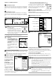
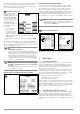
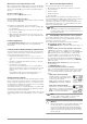
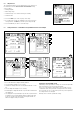
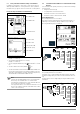
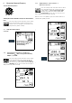
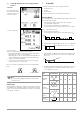
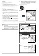
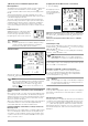
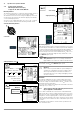
Table Of Contents
- 1 Scope of Delivery
- 2 Application
- 3 Safety Features and Precautions
- 4 Initial Start-Up
- 5 General Notes
- 5.1 Connecting the Instrument
- 5.2 Automatic Settings, Monitoring and Shut-Off
- 5.3 Measurement Value Display and Memory
- 5.4 Testing Earthing Contact Sockets for Correct Connection
- 5.5 Help Function
- 5.6 Setting Parameters or Limit Values using RCD Measurement as an Example
- 5.7 Freely Selectable Parameter Settings or Limit Values
- 5.8 2-Pole Measurement with Fast or Semiautomatic Polarity Reversal
- 6 Measuring Voltage and Frequency
- 7 Testing RCDs
- 8 Testing of Breaking Requirements for Overcurrent Protective Devices, Measurement of Loop Impedance and Determination of Short-Circuit Current (functions ZL-PE and IK)
- 9 Measuring Line Impedance (ZL-N function)
- 10 Earthing Resistance Measurement (RE function)
- 11 Measurement of Insulation Resistance
- 12 Measuring Low-Value Resistance up to 200 Ohm (protective conductor and equipotential bonding conductor)
- 13 Special Functions – EXTRA Switch Position
- 14 Database
- 15 Attaching the Test Probe Holder to the Carrying Strap
- 16 LED Indications, Mains Connections and Potential Differences
- 17 Characteristic Values
- 18 Maintenance
- 19 Appendix
- 19.1 Tables for Determining Maximum or Minimum Display Values in Consideration of Maximum Measuring Uncertainty
- 19.2 At which values should/must an RCD actually be tripped? Requirements for Residual Current Devices (RCDs)
- 19.3 Periodic Testing per DGUV Regulations 3 (formerly BGV A3) – Limit Values for Electrical Systems and Operating Equipment
- 19.4 Optional Accessories (not included)
- 19.5 List of Abbreviations and their Meanings
- 19.6 Keyword Index
- 19.7 Bibliography
- 20 Repair and Replacement Parts Service Calibration Center* and Rental Instrument Service
- 21 Recalibration
- 22 Product Support

12 GMC-I Messtechnik GmbH
If no texts or ID numbers have been entered to the test instrument
when creating structures, ETC generates the missing entries
automatically. These can then be edited in ETC and transferred
back to the test instrument if required.
OFFSET R
L-PE
/ R
N-PE
/ R
L-N
For the measurement of
ZL-PE, ZL-N, RE and
∆U(ZLN), ohmic offset val-
ues RL-PE, RN-PE and RL-N
can be ascertained here,
which then appear in the
footers of the corre-
sponding measuring
menu pages and are sub-
tracted from the mea-
sured values.
➭ Connect the mea-
surement cables to
the respective inputs
and short circuit the
test probes by insert-
ing the test plug into the short-circuiting jumper (PRO-
JUMPER, Z503J).
➭ Start offset measurement by pressing the respective START
key.
The respective offset value cannot be activated or deactivated,
i.e. set to 0, unless all settings are returned to their default values.
There’s a separate offset value for RLO, which can be ascertained
directly in the RLO switch position.
Note
MEASUREMENT OF RL-PE OR RN-P
In the event that phase voltage might be applied to L or N
at the test probe or the measuring adapter during future
measurements, both offset values must be correspon-
dingly determined. Depending on the connection, the
corresponding offset value is then displayed later in the
measuring menu. If no phase voltage is applied, RL-PE
appears as a standard display
Note
In order to ascertain the RLN-OFFSET value for measurement
of ∆U(ZLN):
Connect the test probe to the point of common coupling
(measuring device / meter).
Firmware Revision and Calibration Information (example)
➭ Press any key in order to return to the main menu.
Firmware Update with the MASTER Updater
The layout of the test instruments makes it possible to adapt
device software to the latest standards and regulations. Beyond
this, suggestions from customers result in continuous improve-
ment of test instrument software, as well as new functions.
In order to assure that you can take advantage of all of these ben-
efits without delay, the MASTER Updater allows you to quickly
and completely update your test instrument software on-site.
The user interface can be set to either English, German or Italian.
Note
As a registered user, you’re entitled to download the
MASTER Updater and the current firmware version free of
charge from the myGMC page.
Enter and Select a New Inspector
See also section 5.7 on page 15 regarding the entry of a text.
5 General Notes
5.1 Connecting the Instrument
For systems with earthing contact sockets, connect the instru-
ment to the mains with the KS-PROFITEST INTRO test probes
(Z503L) or with the PRO-Schuko measuring adapter (Z503K).
Voltage between phase conductor L and the PE protective con-
ductor may not exceed 253 V!
Poling at the socket need not be taken into consideration. The
instrument detects the positions of phase conductor L and neu-
tral conductor N and automatically reverses polarity if necessary.
This does not apply to the following measurements:
– Voltage measurement in switch position U
– Insulation resistance measurement
– Low-resistance measurement
If measurement is to be performed at three-phase outlets, in dis-
tribution cabinets or at permanent connections, use the cable set
with KS-PROFITEST INTRO test probes (Z503L) (2-pole), and for
phase sequence testing (3-pole). Connection is established with
the test probes: one at PE or N and the other at L.
5.2 Automatic Settings, Monitoring and Shut-Off
The test instrument automatically selects all operating conditions
which it’s capable of determining itself. It tests line voltage and
frequency. If these lie within their valid nominal ranges, they
appear at the display panel. If they are not within nominal ranges,
prevailing voltage (U) and frequency (f) are displayed instead of U
N
and f
N
.
3h
4
01.17.00
5