
User Manual
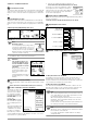
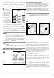
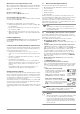
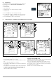
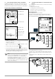
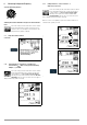
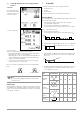
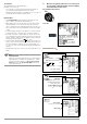
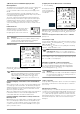
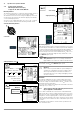
Table Of Contents
- 1 Scope of Delivery
- 2 Application
- 3 Safety Features and Precautions
- 4 Initial Start-Up
- 5 General Notes
- 5.1 Connecting the Instrument
- 5.2 Automatic Settings, Monitoring and Shut-Off
- 5.3 Measurement Value Display and Memory
- 5.4 Testing Earthing Contact Sockets for Correct Connection
- 5.5 Help Function
- 5.6 Setting Parameters or Limit Values using RCD Measurement as an Example
- 5.7 Freely Selectable Parameter Settings or Limit Values
- 5.8 2-Pole Measurement with Fast or Semiautomatic Polarity Reversal
- 6 Measuring Voltage and Frequency
- 7 Testing RCDs
- 8 Testing of Breaking Requirements for Overcurrent Protective Devices, Measurement of Loop Impedance and Determination of Short-Circuit Current (functions ZL-PE and IK)
- 9 Measuring Line Impedance (ZL-N function)
- 10 Earthing Resistance Measurement (RE function)
- 11 Measurement of Insulation Resistance
- 12 Measuring Low-Value Resistance up to 200 Ohm (protective conductor and equipotential bonding conductor)
- 13 Special Functions – EXTRA Switch Position
- 14 Database
- 15 Attaching the Test Probe Holder to the Carrying Strap
- 16 LED Indications, Mains Connections and Potential Differences
- 17 Characteristic Values
- 18 Maintenance
- 19 Appendix
- 19.1 Tables for Determining Maximum or Minimum Display Values in Consideration of Maximum Measuring Uncertainty
- 19.2 At which values should/must an RCD actually be tripped? Requirements for Residual Current Devices (RCDs)
- 19.3 Periodic Testing per DGUV Regulations 3 (formerly BGV A3) – Limit Values for Electrical Systems and Operating Equipment
- 19.4 Optional Accessories (not included)
- 19.5 List of Abbreviations and their Meanings
- 19.6 Keyword Index
- 19.7 Bibliography
- 20 Repair and Replacement Parts Service Calibration Center* and Rental Instrument Service
- 21 Recalibration
- 22 Product Support

GMC-I Messtechnik GmbH 11
Significance of Individual Parameters
Test Instrument On-Time
The period of time after which the test instrument is automatically
shut off can be selected here. This selection has a considerable
influence on the service life and the charging status of the batter-
ies.
LCD Illumination On-Time
The period of time after which LCD illumination is automatically
shut off can be selected here. This selection has a considerable
influence on the service life and the charging status of the batter-
ies.
Submenu: (Rechargeable) Battery Level Query
If (rechargeable) battery voltage has dropped to 8.0 V or less, the
LIMIT LED lights up red and an acoustic signal is generated as well.
Note
Measuring Sequence
If (rechargeable) battery voltage drops
to below 8.0 V during the course of a
measuring sequence, this is only indi-
cated by means of a pop-up window.
Measured values are invalid. The measurement results
cannot be saved to memory.
➭ Press ESC in order to return to the main menu.
Attention!
!
Data, including sequences, are
lost when the language, the pro-
file or the DB MODE is changed,
or if the instrument is reset to de-
fault values!
Back up your structures and
measurement data to a PC
before pressing the respec-
tive key.
The prompt window shown at
the right asks you to confirm
deletion.
User Interface Language (CULTURE)
➭ Select the desired country setup with the appropriate country
code.
Caution: All structures and data will be deleted (see note above)!
Profiles for Distributor Structures (PROFILES)
The profiles are laid out in
a tree structure. The tree
structure for the utilized
PC evaluation program
may differ from that of the
PROFITEST INTRO. For this
reason, the
PROFITEST INTRO provides
the user with the opportu-
nity of adapting this struc-
ture.
Selecting a suitable profile
determines which object
combinations are made
possible. For example,
this makes it possible to
create a distributor which is subordinate to another, or to save a
measurement to a given building.
➭
Select the PC evaluation program you intend to use.
Caution: All structures and data will be deleted (see note above)!
If you have not selected a suitable PC evalua-
tion program and, for example, if measured
value storage to the selected location within the
structure is not possible, the pop-up window
shown at the right appears.
Default Settings (GOME SETTING)
The test instrument is returned to its original default settings when
this key is activated.
Caution: All structures and data will be deleted (see note above)!
Adjust Brightness and Contrast
DB MODE – Database Representation in Text or ID Mode
Creating Structures in the TXT MODE
The database in the test instrument is set to the text mode as a
default feature and “TXT” appears in the header. You can create
structure elements in the test instrument and label them in plain text,
e.g. Customer XY, Distributor XY and Circuit XY.
Creating Structures in the ID MODE
You can work in the ID MODE as an alternative, in which case “ID”
appears in the header. You can create the structure elements in the
test instrument and label them with any desired ID numbers.
Note
When transferring data from the test instrument to ETC at
a PC, ETC always uses the same representation as the
test instrument (TXT or ID mode).
When transferring data from ETC at the PC to the test
instrument, the test instrument always uses the same
representation as ETC.
In other words, the respective data recipient always uses
the same representation as the data transmitter.
Note
Structures can be created in the test instrument in either
the text mode or the ID mode.
In contrast, designations and ID numbers are always
assigned in ETC.
0a
0b
2
3c
3d
3e
3f
Jump back to
Increase brightness
Decrease brightness
Increase contrast
Decrease contrast
previous menu
3g