
User manual

GMC-I Messtechnik GmbH 7
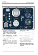
3 Initial Startup
See the connections overview on page 2 for
all connection variants.
3.1 Mains Connection
The test adapter must be connected to the
mains for fault simulation, as well as for indi-
cation by means of the phase LEDs.
Attention!
!
Only one mains power cable (single
or 3-phase) may be connected to the
test adapter at any given time.
Attention!
!
Despite isolation of mains connec-
tions N1 and N2, do not touch open
inlet plug N1 in the case of CEE con-
nection at N2.
➭ Connect the test adapter to the mains
via the single or 3-phase mains power
cable (with the help of the Z570B
adapter for 3-phase 16 A mains or the
Z570C adapter for 3-phase 32 A con-
nection). Refer to the characteristic val-
ues on page 13 for nominal mains
values.
Attention!
!
Single-Phase Mains Connection
For correct phase connection, the
earthing contact plug must inserted
into the mains outlet such that only
the ICCB-IN1 L1 LED lights up.
The ICCB-IN1 PE LED lights up as well
in the case of polarity reversal.
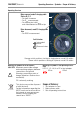
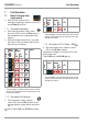
3.2 Testing the LEDs
Single-Phase Mains Connection
➭ Insert the earthing contact plug into the
earthing contact mains outlet, remove it,
rotate it 180° and insert it again.
When connected with correct polarity, only
the ICCB-IN1 L1 LED may light up. When con-
nected with incorrect polarity or if rotated
180°, the ICCB-IN1 L1 and ICCB-IN1 PE LEDs
light up simultaneously.
3-Phase Mains Connection
➭ Connect socket N2 to the 3-phase 16 A
mains with the help of the Z570B
adapter (or the Z570C adapter for 3-
phase 32 A connection).
The ICCB-IN1 L1, L2 and L3 LEDs must light
up.
3.3 Connecting the Mode 2/3 Charging
Cable
The respective charging cable must be con-
nected to the test adapter for all tests.
Connecting a Single-Phase, Mode 2 Charging Cable
➭ Insert the power supply plug of the mode
2 charging cable into earthing contact
outlet IN4, or into IN3 at the test adapter
via an adapter.
➭ Insert the test object’s plug at the vehicle
end into test socket OUT2.
Connecting a 3-Phase,
Mode 2/3 Charging Cable
➭ Insert the plug at the power supply end
of the test object into the outlet of the
adapter connected to IN3, or into IN2
(mode 3 charging cable).
➭ Insert the test object’s plug at the vehicle
end into test socket OUT2.
PROFITEST⏐EMOBILITY Initial Startup