
User manual


GMC-I Messtechnik GmbH 15
Test Adapter Contacting,
3-Phase (400 V)
Protective conductor resistance is tested
between the PE contact at mains connec-
tion N2 and the PE contact at ICCB-IN1
(parallel to IN2, IN3 and IN4).
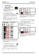
Testing the 3-Phase Connection
➭ Turn the top rotary selector switch (S1) at
the test adapter to the Status C position
(system state: vehicle ready for charging).
➭ Turn the bottom rotary selector switch
(S2) to each switch position*.
With the exclusion of the exceptions speci-
fied in the following table, protective conduc-
tor resistances R
PE
of less than 2 Ω are per-
missible.
This is due to the design of the test
adapter.
The PE connection between OUT1 and OUT2
must also be tested (< 2
Ω
).
9.2.2 Testing Insulation Resistance
Testing is conducted in the respective switch
positions for Status B, C or E and in the
green ON position for 3-phase testing at
short-circuited L-N or L1-L2-L3-N contacts
(for earthing contact and CEE respectively)
• At mains connections N1 and N2
• At the supply end of the test object,
ICCB-IN1
• At the output end of the test object,
ICCB-OUT1
in each case against PE.
The usual limit values apply.
9.2.3 Touch Current Measurement
Touch current measurement is conducted at
the screw connections of the IN sockets
(IN2, IN3 and IN4) with the standard limit val-
ues (I
B
<0,5mA).
Step
Rotary
Switch
Protective Conductor
Resistance R PE,
Permissible
1 <2Ω
2
<2
Ω
3 <2Ω
4
<2
Ω
5 <2Ω
6
<2
Ω
7 <2Ω
8
<2
Ω
9 <2Ω
10
>30M
Ω
11 >30MΩ
PROFITEST⏐EMOBILITY Maintenance