
User manual


14 GMC-I Messtechnik GmbH
9 Maintenance
9.1 Housing Maintenance
No special maintenance is required. Keep
outside surfaces clean and dry. Use a
slightly dampened cloth for cleaning. Avoid
the use of solvents, cleansers and abrasives.
Note!
If the test adapter has not been used
for a long period of time, the switches
may demonstrate increased contact
resistance depending upon storage
conditions.
If this is the case, actuate the
switches several times.
The fuses may only be replaced when the
instrument is voltage-free, i.e. the instrument
must be disconnected from mains supply
power and may not be connected to a mea-
suring circuit. The fuse type must comply
with the specifications in the technical data
or the labeling on the instrument.
9.2 Technical Safety Inspections
Testing per DGUV Rule 3
Subject your test adapter to technical safety
inspections at regular intervals.
The test adapter is designed in accordance
with IEC 61010 as a protection category I
and II test instrument.
Testing of the protective conductor, insula-
tion resistance and touch current is
described in the following subsections.
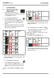
9.2.1 Testing Protective Conductor Resis-
tance R
PE
Test Adapter Contacting, Single-Phase (230 V)
Protective conductor resistance is tested
between the PE contact at the mains plug
(inlet plug N1) and PE contacts ICCB IN1
through IN4.
Testing the Single-Phase Connection
➭ Turn the top rotary selector switch (S1) at
the test adapter to the Status C position
(system state: vehicle ready for
charging).
With the exclusion of the exceptions speci-
fied in the following table, protective conduc-
tor resistances R
PE
of less than 2 Ω are per-
missible. This is due to the design of the test
adapter.
Step
Rotary
Switch
Test
Adapter
ICCB
Protective
Conductor
Resistance RPE,
L1
LED
PE
LED
LED Permissible
1 <2Ω
2 <2Ω
3 <2Ω
4
<2
Ω
5 <2Ω
6 >30MΩ
7
>30M
Ω
8
>30M
Ω
PROFITEST⏐EMOBILITY Maintenance